
Method of encapsulating a projection and making an evacuated cabinet

a technology of projection and encapsulation, which is applied in the direction of dismountable cabinets, other domestic objects, mechanical instruments, etc., can solve the problems of increasing fabrication time and expenses, limiting the working life of non-metallic components, and using adhesives

Inactive Publication Date: 2015-01-29
WHIRLPOOL CORP
View PDF7 Cites 52 Cited by
  • Summary
  • Abstract
  • Description
  • Claims
  • Application Information

AI Technical Summary

Benefits of technology

The invention relates to a method of encapsulating a non-metallic object with a metallic object by placing the non-metallic object within a cavity in the metallic object and using pressure waves or electromagnetic fields to conform the metallic object around the non-metallic object. This creates a secure and reliable connection between the two objects. Additionally, the invention describes a method of making an evacuated structure by positioning metallic elements relative to each other and using a vapor barrier element to create a sealed space between the metallic elements, which can then be emptied of gas.

Problems solved by technology

The use of adhesives may increase fabrication time and expenses, limit the working life of the non-metallic component, contribute to a detrimental appearance from improper alignment of components, and increase waste.
In some methods, the tubs are welded together, which may provide a thermal path negatively impacting the insulating qualities of the cabinet.
However, the integrity of an adhesive is not adequately predictable.

Method used


Image

  • Method of encapsulating a projection and making an evacuated cabinet
  • Method of encapsulating a projection and making an evacuated cabinet
  • Method of encapsulating a projection and making an evacuated cabinet

Examples


first embodiment

[0075]FIGS. 15A-15F illustrate different fabrication techniques for a cabinet providing both refrigerator and freezer chambers. In FIG. 15A, a refrigerator cabinet shell 300 includes a freezer cabinet 302 and a refrigerator cabinet 306. The freezer cabinet 302 has an inner metallic tub 304 defining a freezer chamber 314 and an outer metallic tub 310 that are coupled as previously described by a crimped portion 234. The refrigerator cabinet 306 has an inner metallic tub 308 defining a refrigerator chamber 316 and an outer metallic tub 318 also coupled by a crimped portion 234. The cabinets 302, 306 may be coupled together in a suitable manner, such as by adhesives, welding, fasteners, and the like.

embodiment 320

[0076]FIG. 15B illustrates an embodiment 320 that may comprise a single cabinet 322 defining a chamber 328 having an outer metallic tub 323 and an inner metallic tub 324 coupled through a crimped portion 234. The cabinet 322 may be separated into a freezer section and a refrigerator section through an interior insulated wall 326.

embodiment 330

[0077]FIG. 15C illustrates an embodiment 330 of a cabinet that may have a single outer metallic tub 336 enclosing a freezer cabinet 332 and a refrigerator cabinet 334. The refrigerator cabinet may include an inner metallic tub 340. The freezer cabinet may include an inner metallic tub 338. The inner metallic freezer tub 338 may be coupled with the outer metallic tub 336 through a first portion of the crimped portion 234. Similarly, the inner metallic refrigerator tub 340 may be coupled with the outer metallic tub 336 through a second portion of the crimped portion 234. Finally, the inner metallic freezer tub 338 may be coupled with the inner metallic refrigerator tub 340 through a crimped portion 342.

[0078]FIG. 15D is similar to FIG. 15A in that a single refrigerator cabinet shell 350 may include a vertically disposed freezer cabinet 352 and a vertically disposed refrigerator cabinet 354. The freezer cabinet 352 may include an outer metallic tub 358 and an inner metallic tub 356. Th...


PUM

PropertyMeasurementUnit
speedsaaaaaaaaaa
speedsaaaaaaaaaa
pressureaaaaaaaaaa

Abstract

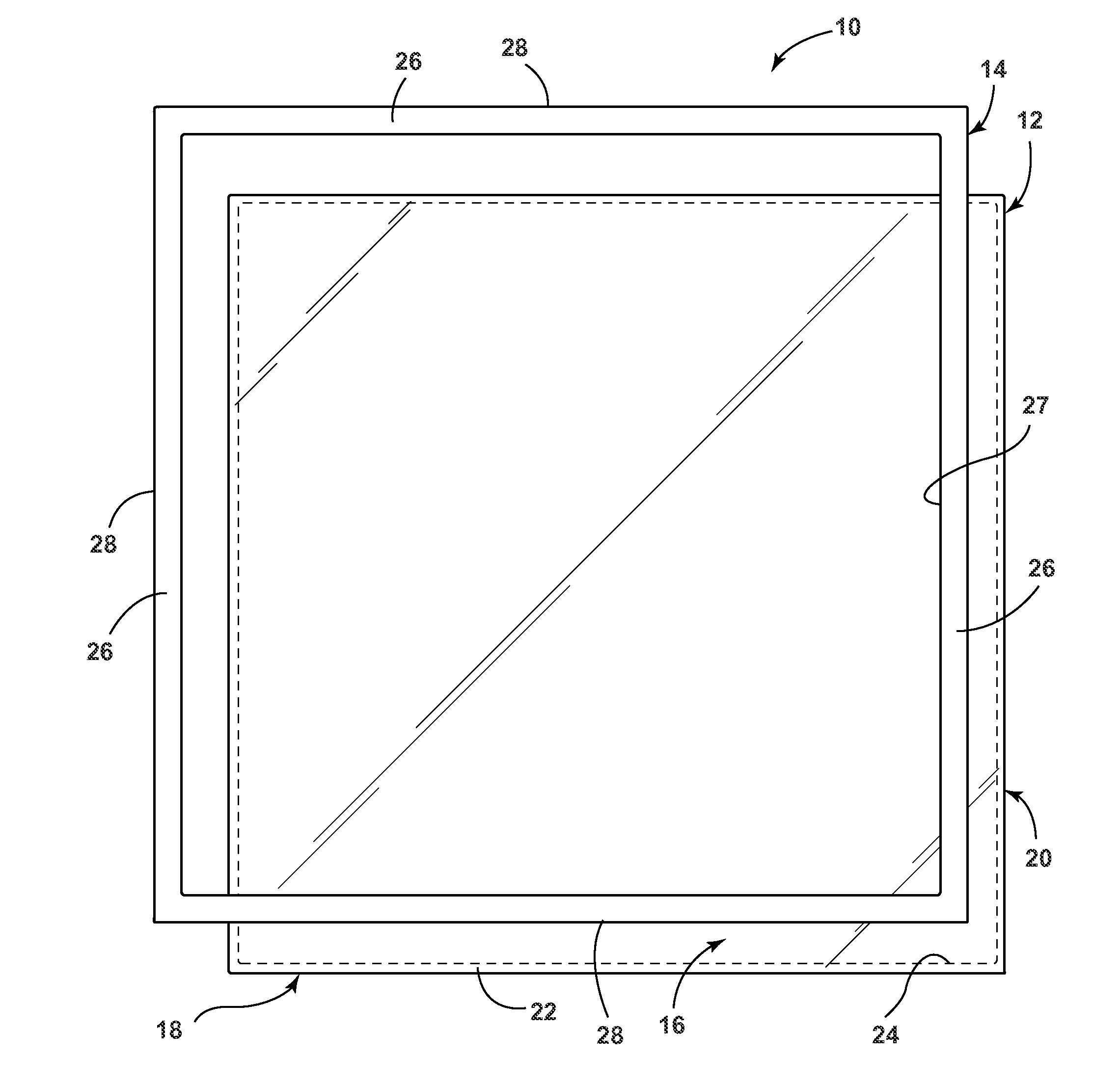
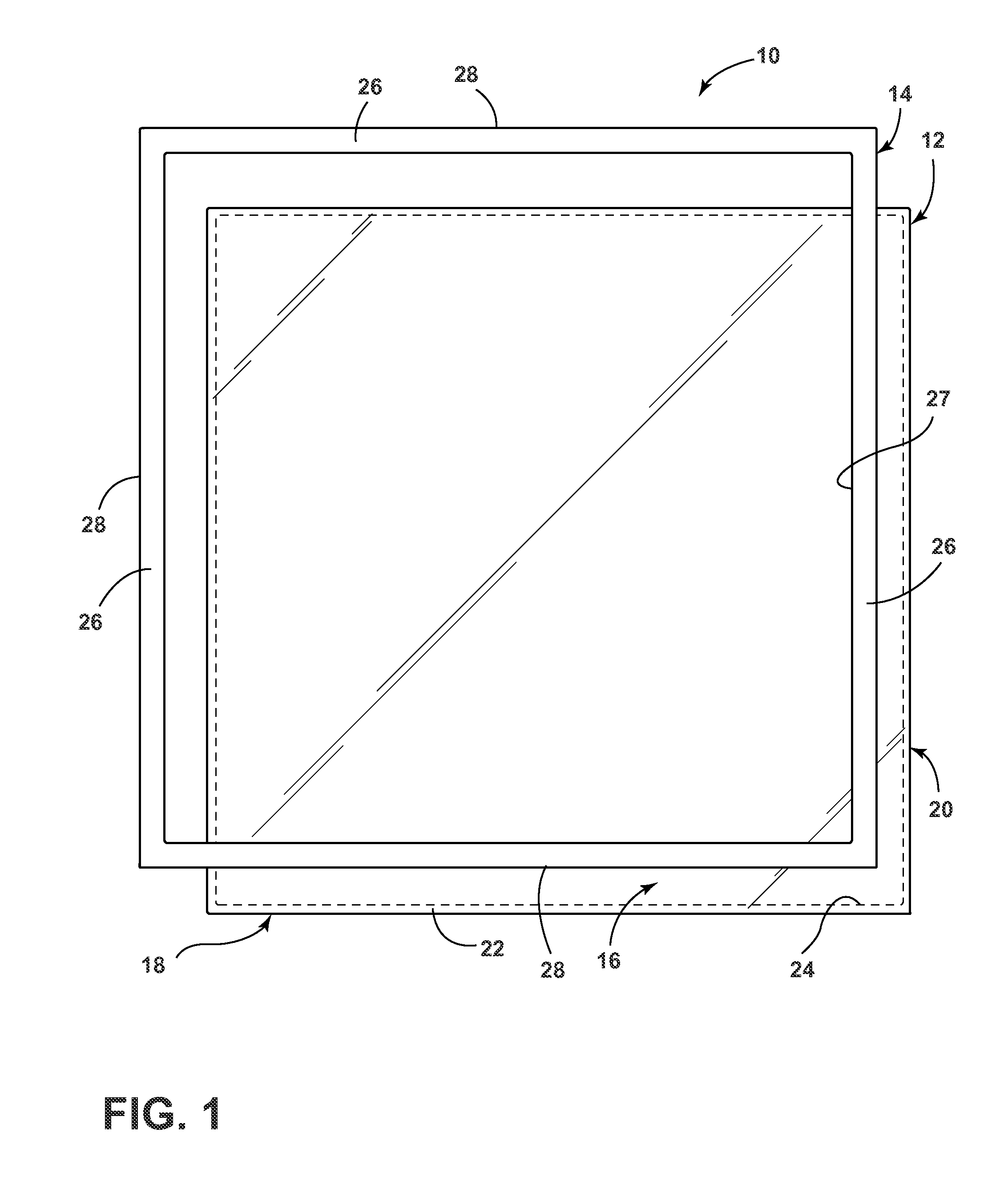
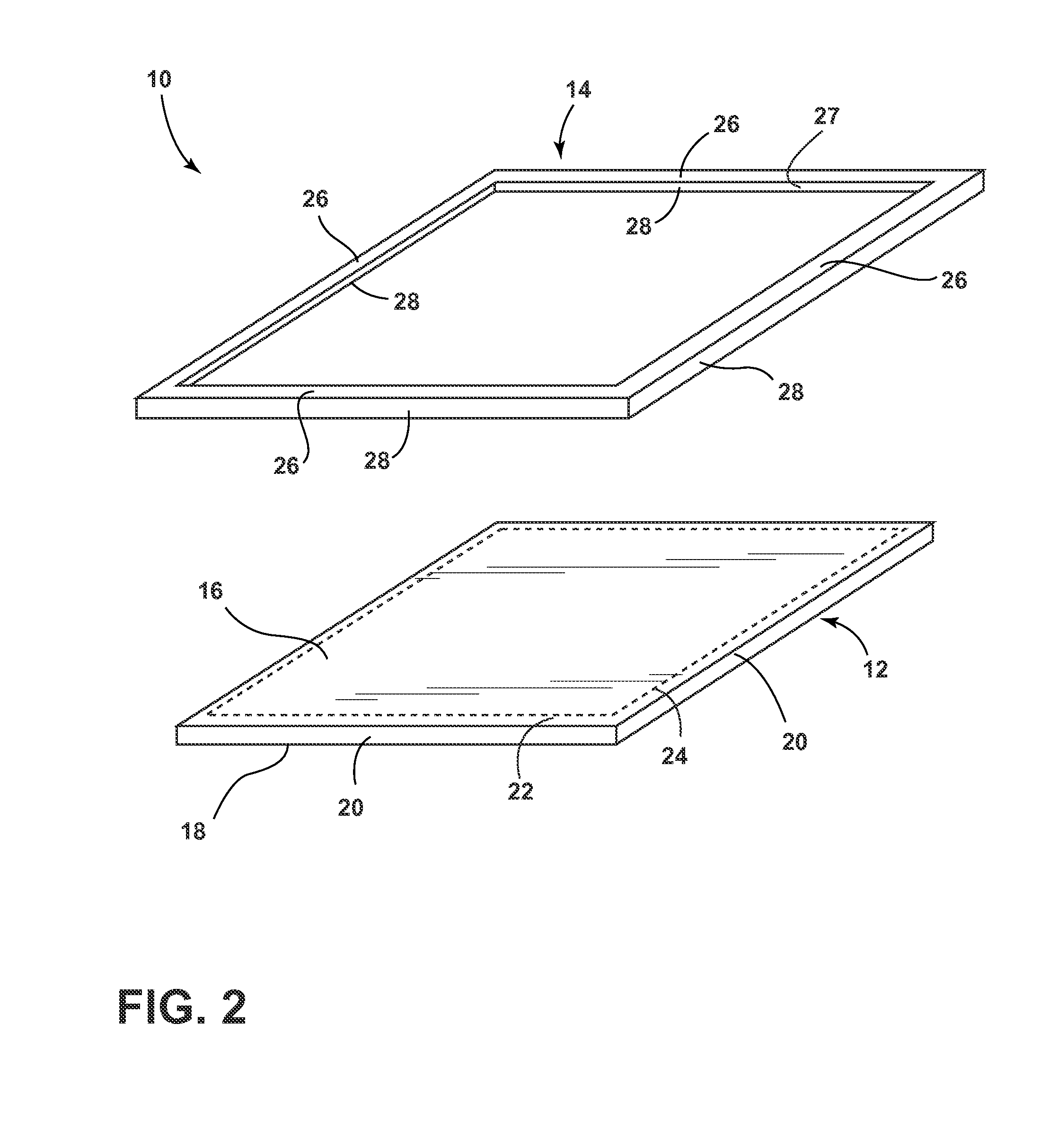
The invention relates to a method of using high velocity metal forming to encapsulate a projection of a non-metallic article by a metallic article and a method of crimping terminal flanges defining an interstitial space therebetween, while trapping a vapor barrier element between the terminal flanges, thereby hermetically sealing the interstitial space.

Description

CROSS-REFERENCE TO RELATED APPLICATIONS[0001]The present application claims the benefit of U.S. Provisional Patent Application No. 61 / 774,625, filed Mar. 8, 2013, and U.S. Provisional Patent Application No. 61 / 774,630, filed Mar. 8, 2013, which are incorporated by reference herein in their entirety.BACKGROUND OF THE INVENTION[0002]Encapsulation of a projection may be used for a variety of purposes. In cases where the projection is a peripheral edge of a planar element, such as refrigerator shelves, cooktops, washer lids, and the like, the encapsulation may provide protection to the peripheral edge and / or may provide a mounting structure. The use of adhesives may increase fabrication time and expenses, limit the working life of the non-metallic component, contribute to a detrimental appearance from improper alignment of components, and increase waste.[0003]Evacuated structures are often used in environments where it is desirable to thermally insulate the interior of the structure fro...

Claims


Application Information

Patent Timeline
Patent Type & Authority Applications(United States)
IPC IPC(8): B29C65/14B29C65/44
CPCB29C65/14B29L2031/762B29K2105/253B29C65/44F16B12/06A47F3/04A47B47/025
Inventor CRAVENS, CHARLES R.GIANNI, CHRISTIANGUARINO, JAMES C.L.KUEHL, STEVEN J.MEDDLES, JOHN E.WU, GUOLIAN
Owner WHIRLPOOL CORP
Learn More