Organic electroluminescent element

Inactive Publication Date: 2015-01-29
PANASONIC CORP
View PDF1 Cites 14 Cited by
  • Summary
  • Abstract
  • Description
  • Claims
  • Application Information

AI Technical Summary

Benefits of technology

[0014]It is possible according to the present invention by forming a light-outcoupling layer to improve light-outcoupling efficiency and also to suppress water penetration effectively, as the light-outcoupling layer has a thi

Problems solved by technology

Degradation of an organic layer causes troubles such as insufficient light emission efficiency and thus deterioration of reliability of the organic EL element.
However, when a light-outcoupling layer for example of a plastic or resin material is formed

Method used


Image

  • Organic electroluminescent element
  • Organic electroluminescent element
  • Organic electroluminescent element

Examples


Embodiment Construction

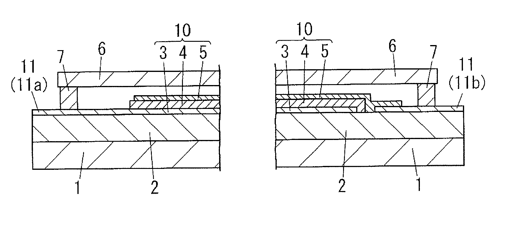
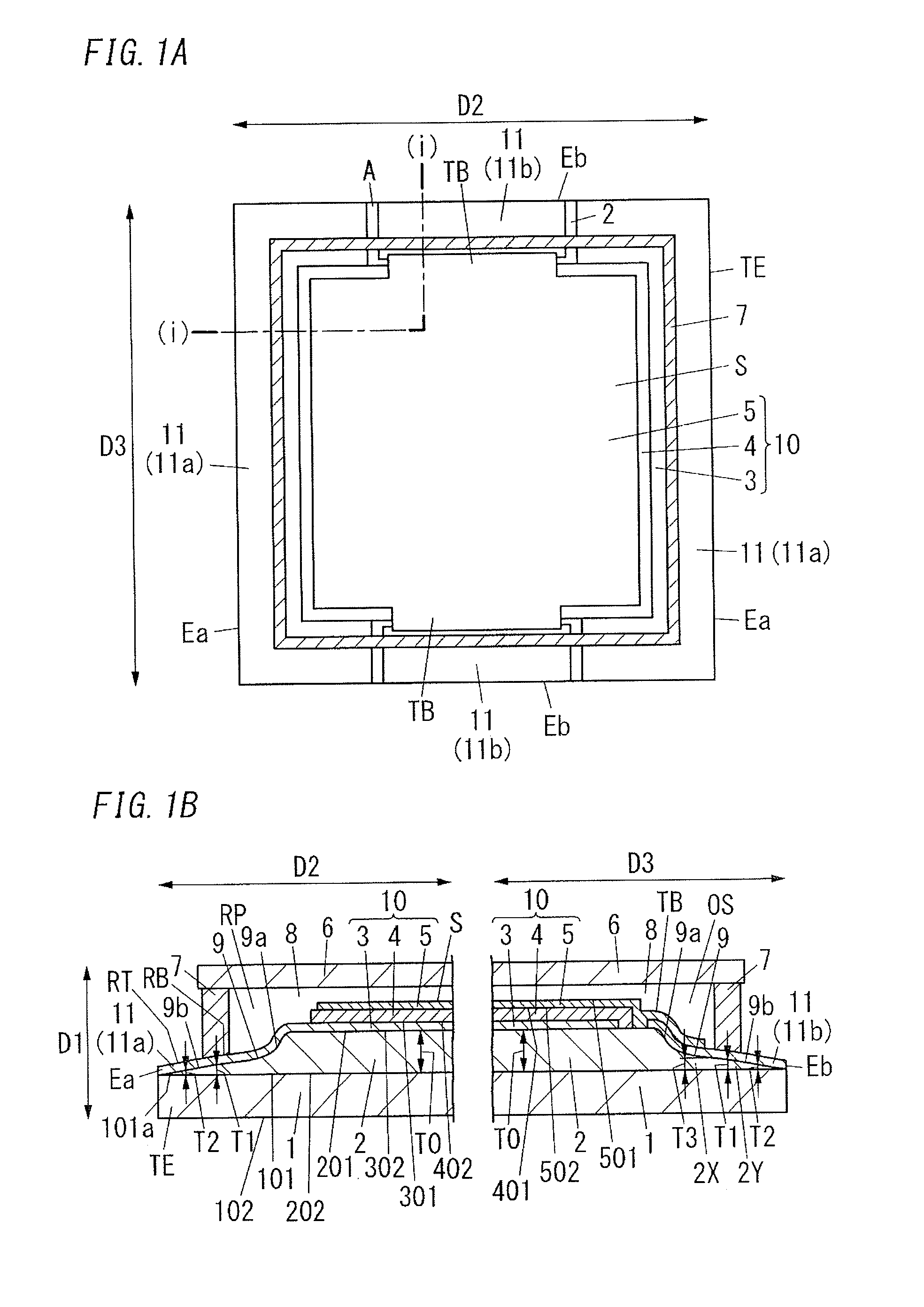
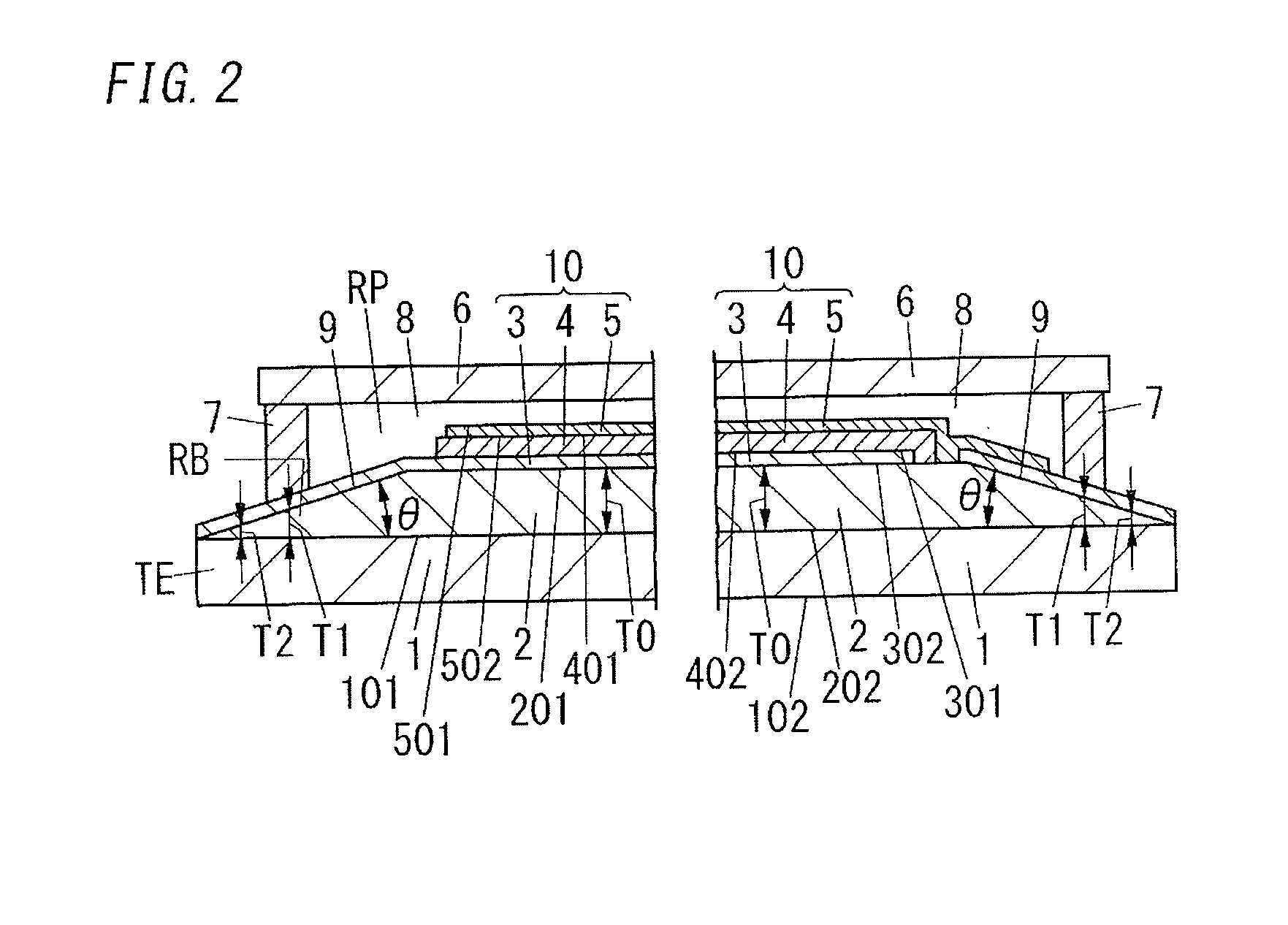
[0026]FIGS. 11A to 11B show an example of the organic EL element that contributed to creation of the organic electroluminescent element (organic EL element) according to the present invention. The organic EL element has a light-outcoupling layer 2 formed on the surface of a transparent substrate 1. An electroluminescent laminate 10 having a transparent first electrode 3, an organic layer 4 and a second electrode 5 which are arranged in that order is formed on the surface of the light-outcoupling layer 2. In addition, a covering substrate 6 facing the transparent substrate 1 is adhered to the transparent substrate 1 via an adhesive sealing portion 7 surrounding the electroluminescent laminate 10. Further, the connection electrode 11, which includes a first connection electrode 11a electrically connected to the first electrode 3 and a second connection electrode 11b electrically connected to the second electrode 5, is formed so as to extend from inside the surrounded region to outside...


PUM


Abstract

The organic electroluminescent element has a transparent substrate, a transparent first electrode, an organic layer, a second electrode, and a light-outcoupling layer. The light-outcoupling layer is formed between the transparent substrate and the first electrode. The first electrode, the organic layer and the second electrode constitute an electroluminescent laminate. A covering substrate facing the transparent substrate is adhered to the surface of the transparent substrate via an adhesive sealing portion surrounding the periphery of the electroluminescent laminate. A connection electrode extending outward from inside a surrounded region where the electroluminescent laminate is covered with the covering substrate is formed at least on the surface of the light-outcoupling layer. The average thickness of the light-outcoupling layer in an adhesion region where the adhesive sealing portion is formed is smaller than the thickness in the central region where the electroluminescent laminate is formed.

Description

TECHNICAL FIELD[0001]The present invention relates to an organic electroluminescent element.BACKGROUND ART[0002]Recently, organic electroluminescent elements (hereinafter, referred to also as “organic EL elements”) have been used in various applications including lighting panels. An example of the organic EL element known is an EL element having a transparent substrate and a laminate of a transparent first electrode (anode), an multi-layered organic layer containing a light-emitting layer, and a second electrode (cathode) formed in that order on the surface of the transparent substrate, as described in JP-A No. 2005-108824. In organic EL elements, the light generated in the light-emitting layer when voltage is applied between the anode and the cathode passes through the transparent electrode and the substrate and is emitted outward.[0003]Generally in organic EL elements, the intensity of the light from the light-emitting layer is decreased for example by absorption in the substrate ...

Claims


Application Information

Patent Timeline
IPC IPC(8): H01L51/52
CPCH01L51/5275H01L51/5246H10K50/805H10K50/841H10K50/854H10K50/858H10K2102/351H10K50/8426
Inventor ICHIHARA, TSUTOMUSANAGAWA, YOSHIHARUIDE, NOBUHIROKUBOTA, HIROFUMI
Owner PANASONIC CORP
Why Eureka
Try Eureka