Organic electroluminescence element and method of manufacturing the same

a technology light-emitting areas, which is applied in the direction of sustainable manufacturing/processing, thermoelectric devices, and final product manufacturing, etc., can solve the problems of difficult to effectively enhance the light-emitting efficiency of organic el elements having a large light-emitting area, and achieve enhanced light-outcoupling efficiency, effective light-outcoupling efficiency, and enhanced light-outcoupling efficiency

Inactive Publication Date: 2016-03-03
PANASONIC INTELLECTUAL PROPERTY MANAGEMENT CO LTD
View PDF8 Cites 11 Cited by
  • Summary
  • Abstract
  • Description
  • Claims
  • Application Information

AI Technical Summary

Benefits of technology

[0005]The objective of the present disclosure is to provide an organic electroluminescence element with an effectively improved light-outcoupling efficiency and a method of manufacturing the same.
[0006]The present disclosure relates to an organic electroluminescence element. The organic electroluminescence element includes: a first substrate on a light extraction side of the organic electroluminescence element; a second substrate opposite the first substrate; and an organic light-emitting laminate between the first substrate and the second substrate. The first substrate includes a doped region in a surface close to the organic light-emitting laminate, the doped region being doped with a dopant for causing change in a refractive index of the first substrate to enhance a light-outcoupling efficiency.
[0007]The present disclosure relates to a method of manufacturing an organic electroluminescence element. The method is suitable for manufacturing the above-mentioned organic electroluminescence element, and includes: implanting, into a surface of a first substrate, a dopant for causing change in a refractive index of the first substrate to enhance a light-outcoupling efficiency; and diffusing an implanted dopant.
[0008]According to the present disclosure, the doped region is present in the first substrate on the light extraction side, and hence the light-outcoupling efficiency may be effectively improved.

Problems solved by technology

However, in the method of this literature, the light-emitting layer and the uneven structure are not overlapped with each other, and hence it is difficult to effectively enhance the light-outcoupling efficiency of the organic EL element having a large light-emitting area.

Method used


Image

  • Organic electroluminescence element and method of manufacturing the same
  • Organic electroluminescence element and method of manufacturing the same
  • Organic electroluminescence element and method of manufacturing the same

Examples


Embodiment Construction

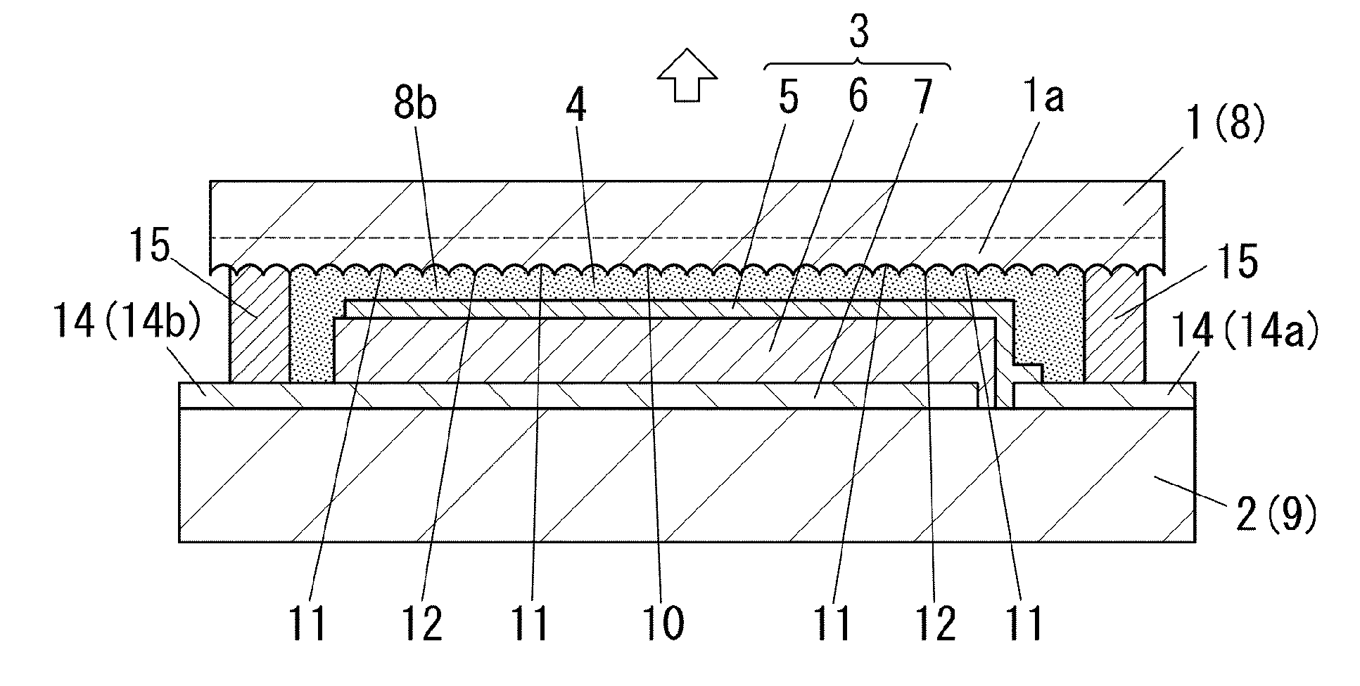
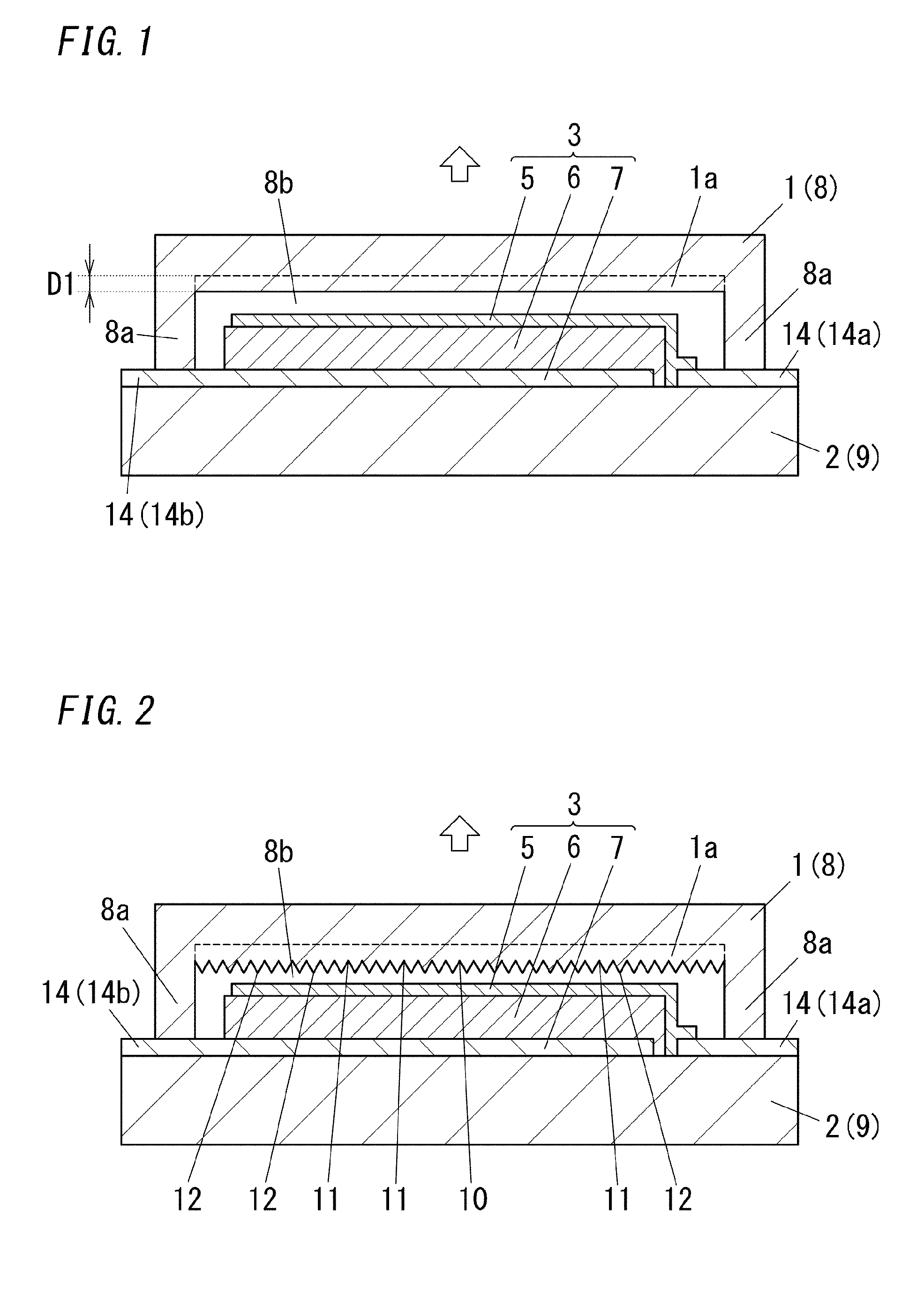
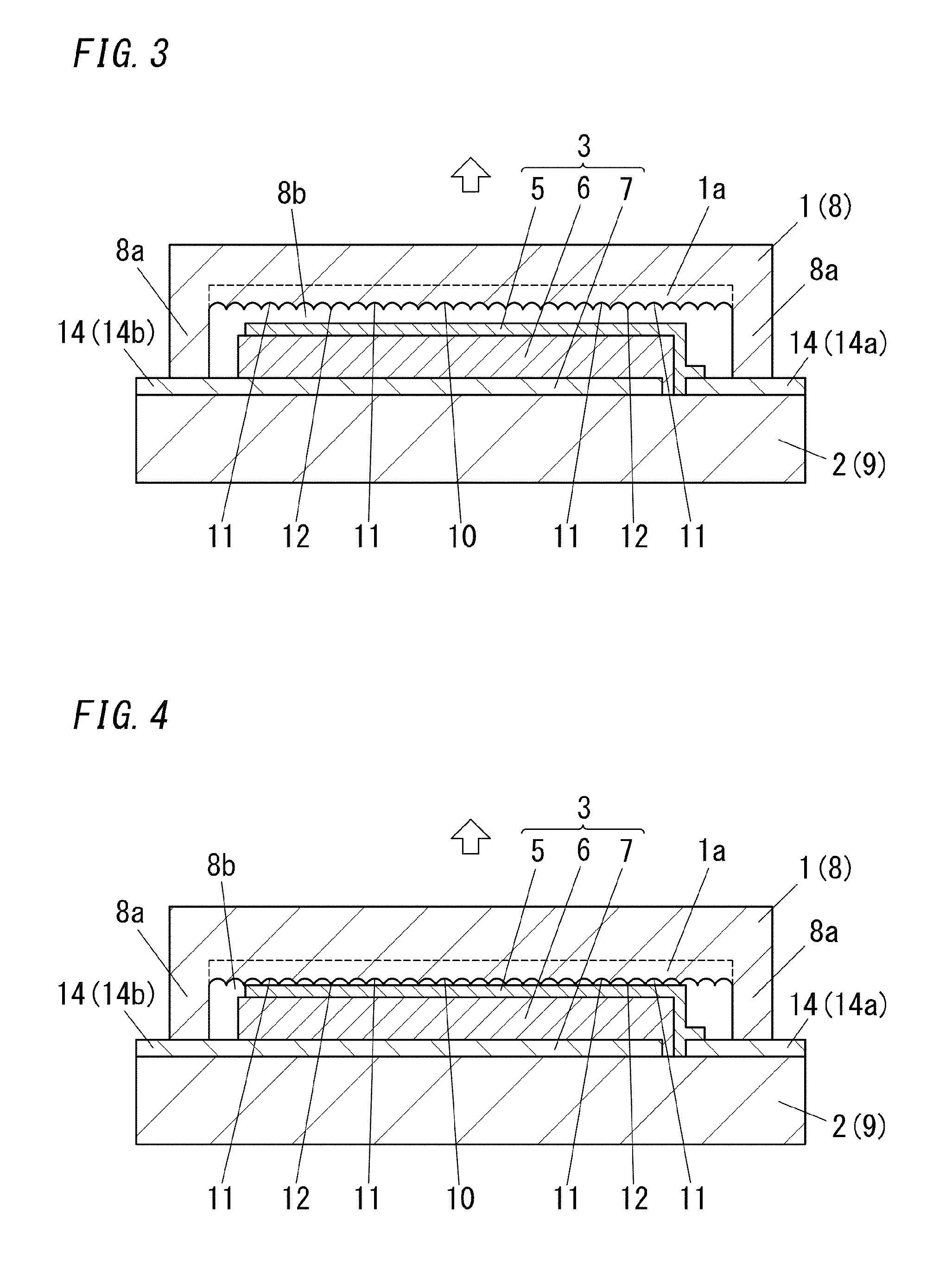
[0023]The present disclosure relates to an organic electroluminescence element (organic EL element). The organic EL element includes a first substrate 1 on a light extraction side of the organic EL element, a second substrate 2 opposite the first substrate 1, and an organic light-emitting laminate 3 between the first substrate 1 and the second substrate 2. The first substrate 1 includes a doped region 1a in the surface close to the organic light-emitting laminate 3, and the doped region 1a is doped with a dopant for causing change in a refractive index of the first substrate 1 to enhance a light-outcoupling efficiency. In this organic EL element, the doped region 1a is formed in the first substrate 1 on the light extraction side, and hence total reflection of light emitted from a light-emitting layer can be suppressed. Therefore, the light-outcoupling efficiency can be easily and effectively improved.

[0024]FIG. 1 shows an example of the organic electroluminescence element (organic E...


PUM


Abstract

The disclosure relates to an organic electroluminescence element including: a first substrate on a light extraction side thereof; a second substrate opposite the first substrate; and an organic light-emitting laminate between the first substrate and the second substrate. The first substrate includes a doped region in a surface close to the organic light-emitting laminate, the doped region being doped with a dopant for causing change in a refractive index of the first substrate to enhance a light-outcoupling efficiency.

Description

TECHNICAL FIELD[0001]The present disclosure relates to an organic electroluminescence element and a method of manufacturing the same.BACKGROUND ART[0002]There has been generally known an organic electroluminescence element (hereinafter also referred to as “organic EL element”) having a structure in which, between a pair of substrates, an organic light-emitting laminate is situated, which is formed by stacking an anode, a hole transport layer, a light-emitting layer, an electron injection layer, a cathode, and the like. In the organic EL element, a voltage is applied between the anode and the cathode so that light emitted from the light-emitting layer emerges outside through a light-transmissive substrate.[0003]In the organic EL element, it is important to increase an amount of light which is emitted from the light-emitting layer and emerges outside. In the organic EL element, in general, part of light traveling from the light-emitting layer toward the outside is confined inside the ...

Claims


Application Information

Patent Timeline
Patent Type & Authority Applications(United States)
IPC IPC(8): H01L51/52H01L51/00H01L51/56
CPCH01L51/5275H01L51/56H01L51/0096H01L2251/533H01L51/5268H01L51/5246H01L2251/5315H01L51/5271H01L51/524Y02E10/549Y02P70/50H10K50/841H10K50/854H10K50/858H10K50/856H10K50/8426H10K71/00H10K77/10H10K2102/3026H10K2102/3035
Inventor YOSHIHARA, TAKAAKIAOKI, MOTONOBUANJIKI, TAKASHI
Owner PANASONIC INTELLECTUAL PROPERTY MANAGEMENT CO LTD
Why Eureka
Try Eureka