Coupling device for a multi-phase converter

a multi-phase converter and coupling device technology, applied in the direction of electric variable regulation, process and machine control, instruments, etc., can solve problems such as affecting the operation of multi-phase converters, and achieve the effects of reducing the magnetic modulation of the coupling module, small core loss, and large coupling module loss

Active Publication Date: 2015-01-29
ROBERT BOSCH GMBH
View PDF8 Cites 2 Cited by
  • Summary
  • Abstract
  • Description
  • Claims
  • Application Information

AI Technical Summary

Benefits of technology

[0007]Provision can furthermore be made for two windings and therefore two sections of a conductor loop provided for the phase to penetrate a coupling module per phase. As a result, a reduced magnetic modulation of the coupling module by means of voltage-time integrals, e.g. voltage-time areas, of the magnetic fluxes of the phases occurs as well as very small core losses. As a rule, it is not necessary to cool down the coupling modules. Each conductor loop for a phase has a metallic wire which is wrapped with insulating material. A voltage for the phase is applied to each conductor loop. In addition, a current provided for the phase flows through each conductor loop.
[0008]Each through-hole of a coupling module, which, for example, comprises two of such through-holes, can furthermore have a large winding window, into which a piece of copper having a large cross section can be introduced, whereby winding resistances in the range of less than 1 mOhm to a few mOhm can be facilitated.
[0010]The multi-phase converter can be designed as a low voltage converter and can be used in the automotive field, wherein high performance rates and efficiency levels can be achieved. Conductor loops for providing the phases can be wires made from copper which have a small electrical resistance, whereby the level of efficiency of the four-phase converter is increased. The wires can furthermore be coated with plastic or lacquer. The four-phase converter furthermore has low stand-by losses and thereby a high level of efficiency at low loads. A high level of dynamics can be achieved by the coupling of the phases provided by the invention. A leakage flux of the typically four phases of the multi-phase converter designed as a four-phase converter can be simply adapted by the dimensioning of a slot between the adjacent through-holes, whereby the electromagnetic compatibility can be adapted to the load requirements. In addition, the conductor loops are short because each phase is led out of that coupling module exactly at the point where it again penetrates said module. As a result, a phase can be directly connected with and / or via a capacitor to a switching cell which promotes the electromagnetic compatibility.
[0012]Because only four phases are coupled in this embodiment, an excessively high coupling is thereby intended to be prevented in contrast to multi-phase converters comprising more than four phases. As a result, problems with regard to the electromagnetic compatibility can be reduced by too good a coupling. This is made possible by means of an additional leakage path for a leakage flux. The four-phase converter is furthermore simply and compactly constructed, whereby manufacturing costs can be saved. A beginning of a conductor loop for respectively one phase that is guided into the four-phase converter and an end of the conductor loop that is guided out of said four-phase converter lie spatially in close proximity to one another; thus enabling disadvantages for the electromagnetic compatibility to be reduced in comparison to sections of a conductor loop through which the phase is guided and which are spaced too far apart from one another. In the event of the four-phase converter being operated at idle, high core losses can furthermore be prevented and correspondingly a degree of efficiency can be improved at low load conditions.

Problems solved by technology

A current ripple through the magnetic coupling, which is generated by each phase, can however impair the operation of the multi-phase converter.

Method used


Image

  • Coupling device for a multi-phase converter
  • Coupling device for a multi-phase converter
  • Coupling device for a multi-phase converter

Examples


first embodiment

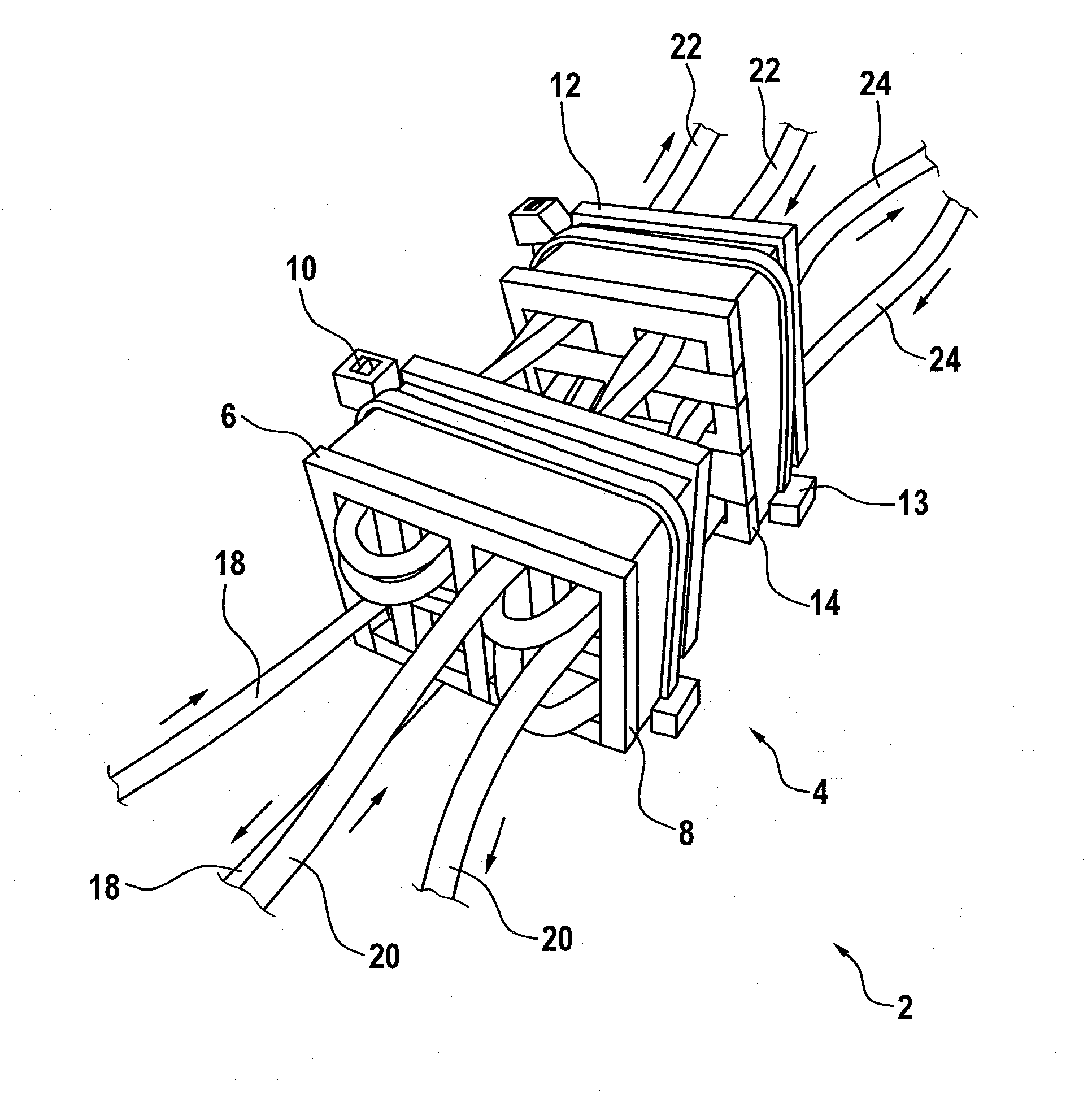
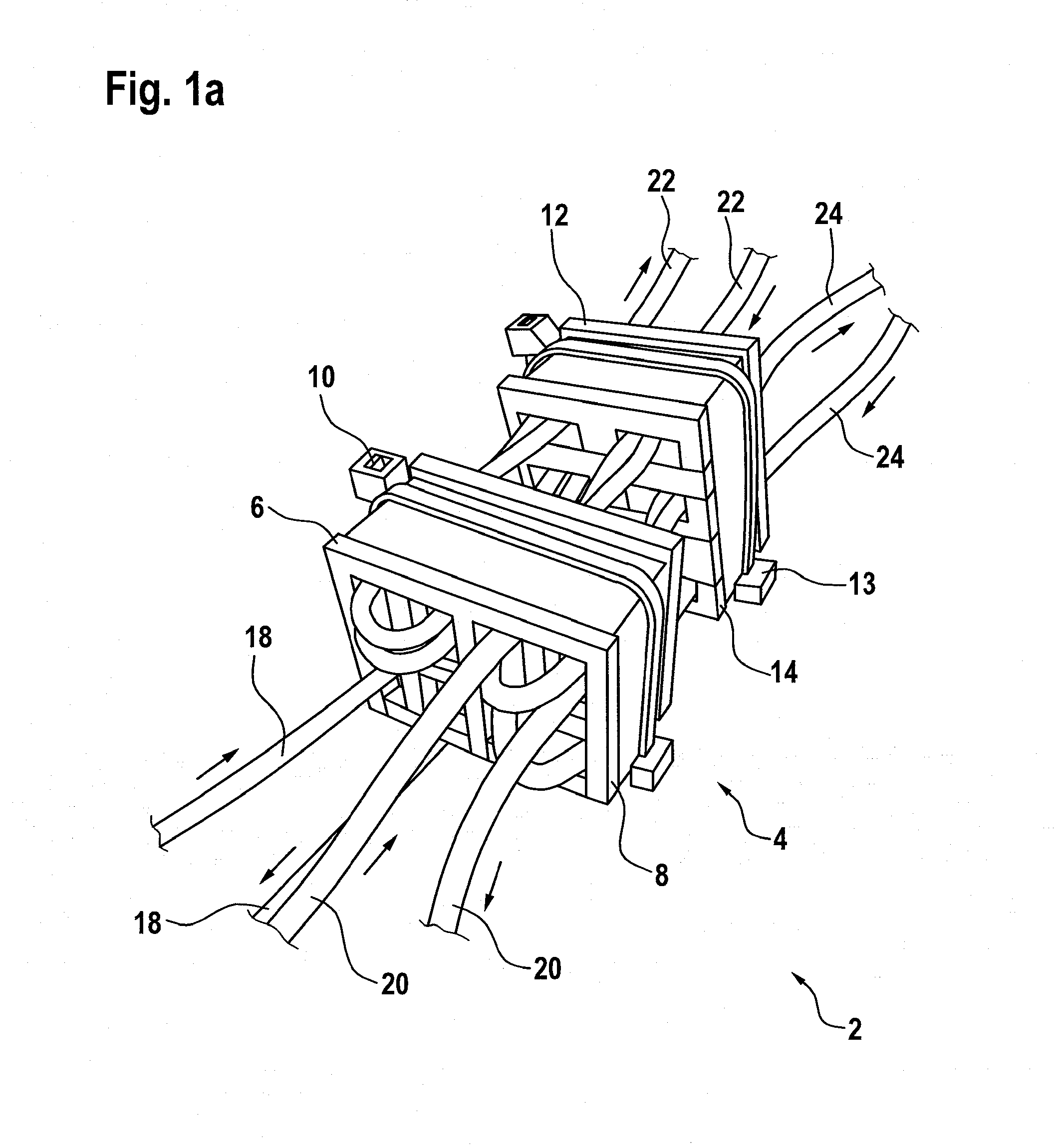
[0023]the multi-phase converter, which is designed here as a four-phase converter and is schematically depicted in FIG. 1, comprises a coupling device 4 for four phases which have electrical voltages. The voltage of a phase and a current which flows through the phase can vary for a phase. Thus, the voltage of a phase can be a DC voltage with a superimposed AC component which can be a few percent of a value of the DC voltage. The voltage of a phase can be embodied as a clocked DC voltage.

[0024]The coupling device 4 thereby comprises a first and a second coupling module 6, 8 which can be magnetically decoupled from one another and consequently do not have to be magnetically coupled to one another. In addition, the coupling device 4 comprises a third and a fourth coupling module 12, 14 which likewise can be magnetically decoupled from one another and consequently do not have to be magnetically connected to one another.

[0025]In addition, FIG. 1 shows two bands 10, 13 by means of which c...

second embodiment

[0111]The four coupling modules 64, 66, 68, 70 are constructed and therefore designed similarly to those coupling modules 34, 36, 38, 40 of the coupling device 30 which were already presented with the aid of FIG. 2. In this regard, each coupling module 64, 66, 68, 70, as viewed from the front, has a first through-hole 6401, 6601, 6801, 7001 at the top left, a second through-hole 6402, 6602, 6802, 7002 at the top right, a third through-hole 6403, 6603, 6803, 7003 at the lower left and a fourth through-hole 6404, 6604, 6804, 7004 at the lower right. In the first coupling module 64, the first and the second through-hole 6401, 6402 are thereby connected to one another via a first slot 6405 as well as the third and the fourth through-hole 6403, 6404 via a second slot 6406. The same applies to the second coupling module 66 in which the first and the second through-hole 6601, 6602 are connected to one another via a first slot 6605 as well the third and the fourth through-hole 6603, 6604 vi...

third embodiment

[0151]In the third embodiment, each conductor loop 72, 74, 76, 78 is in each case guided once through a coupling module 64, 66, 68, 70 and therefore through a plane.

[0152]At least in the first, third and fourth embodiment, structures comprising one, two or multiple feed-throughs of a conductor loop 18, 20, 22, 24, 72, 74, 76, 78, 118, 120 through a coupling module 18, 20, 22, 24, 72, 74, 76, 78, 90 are conceivable, wherein the number of feed-throughs is typically in the small single digit range. In regard to the coupling module 90 from FIG. 4, which is designed for the fourth embodiment of the coupling device, each conductor loop 118, 120 penetrates two through-holes 110, 112, 114, 116, wherein respectively one conductor loop 118, 120 penetrates a first through-hole 110, 112, 114, 116 in a first direction and a further second through-hole 110, 112, 114, 116 in a second, opposite direction.

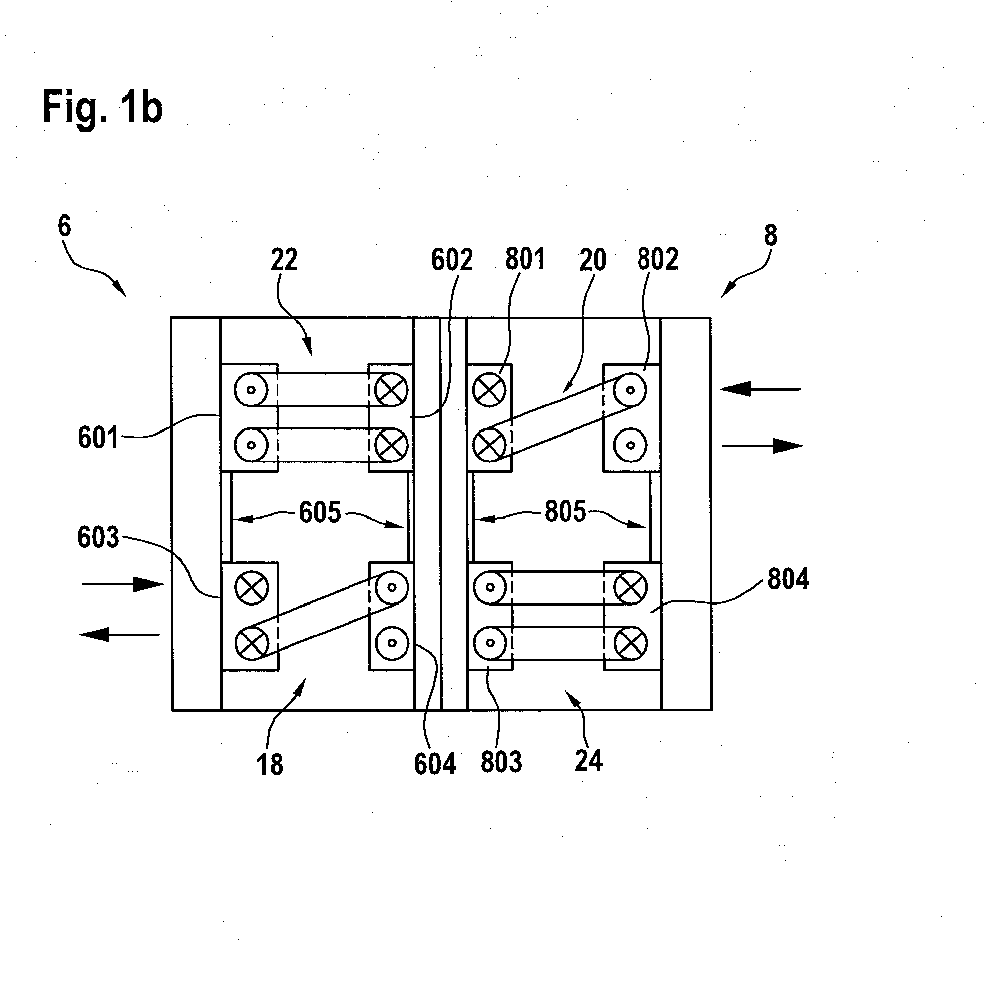
[0153]In the first embodiment of the coupling device 4, sections of conductor loops 18, 20, 22,...


PUM

PropertyMeasurementUnit
inductancesaaaaaaaaaa
thicknessaaaaaaaaaa
inductancesaaaaaaaaaa

Abstract

The invention relates to a coupling device (4) for four phases of a multi-phase converter (2). Said coupling device (4) includes four coupling modules (6, 8, 12, 14), each of which encompasses four parallel through-holes. At least one section of a conductor loop (18, 20, 22, 24) for a phase. At least one section of a conductor loop (18, 20, 22, 24) for a phase penetrates a through-hole of a coupling module (6, 8, 12, 14), sections of conductor loops (18, 20, 22, 24) for at least two phases penetrating all four through-holes of a coupling module (6, 8, 12, 14).

Description

BACKGROUND OF THE INVENTION[0001]The invention relates to a coupling device for a multi-phase converter and a multi-phase converter.[0002]A power converter, which can also be referred to as a direct current converter or DC-DC converter, is designed to convert a DC voltage at an input into a DC voltage having another voltage level. Such a power converter can also be designed as a multi-phase converter comprising coupled inductors. Coupled multi-phase converters comprise a plurality of phases, wherein each phase is passed through a current carrying conductor, said phases being coupled to one another by means of magnetic coupling means. A current ripple through the magnetic coupling, which is generated by each phase, can however impair the operation of the multi-phase converter. That is why sections of the individual conductors are to be suitably arranged relative to one another in order, for example, to prevent disadvantages from occurring in an electromagnetic compatibility.[0003]The...

Claims


Application Information

Patent Timeline
Patent Type & Authority Applications(United States)
IPC IPC(8): H01F30/12G05F3/08H01F38/14H02M1/00
CPCH01F30/12G05F3/08H01F38/14H01F3/14H01F2038/026H02M3/1584H02M3/1586Y02B70/10H01F27/38H01F30/14H02M3/22H02M1/0048
Inventor SCHINZEL, MIRKODRAESE, NILS
Owner ROBERT BOSCH GMBH
Why Eureka
Try Eureka