
Robot apparatus and robot controlling method

a robot and robot technology, applied in the field of robot apparatus, can solve the problems of deviating from difficult to return to the original target position, and complex movement of robots at high speed

Active Publication Date: 2015-02-12
CANON KK
View PDF9 Cites 21 Cited by
  • Summary
  • Abstract
  • Description
  • Claims
  • Application Information

AI Technical Summary

Benefits of technology

The present invention is about a robot that has several joints and a way to control it. The technical effects of this invention include improving the robot's precision and efficiency in performing complex tasks.

Problems solved by technology

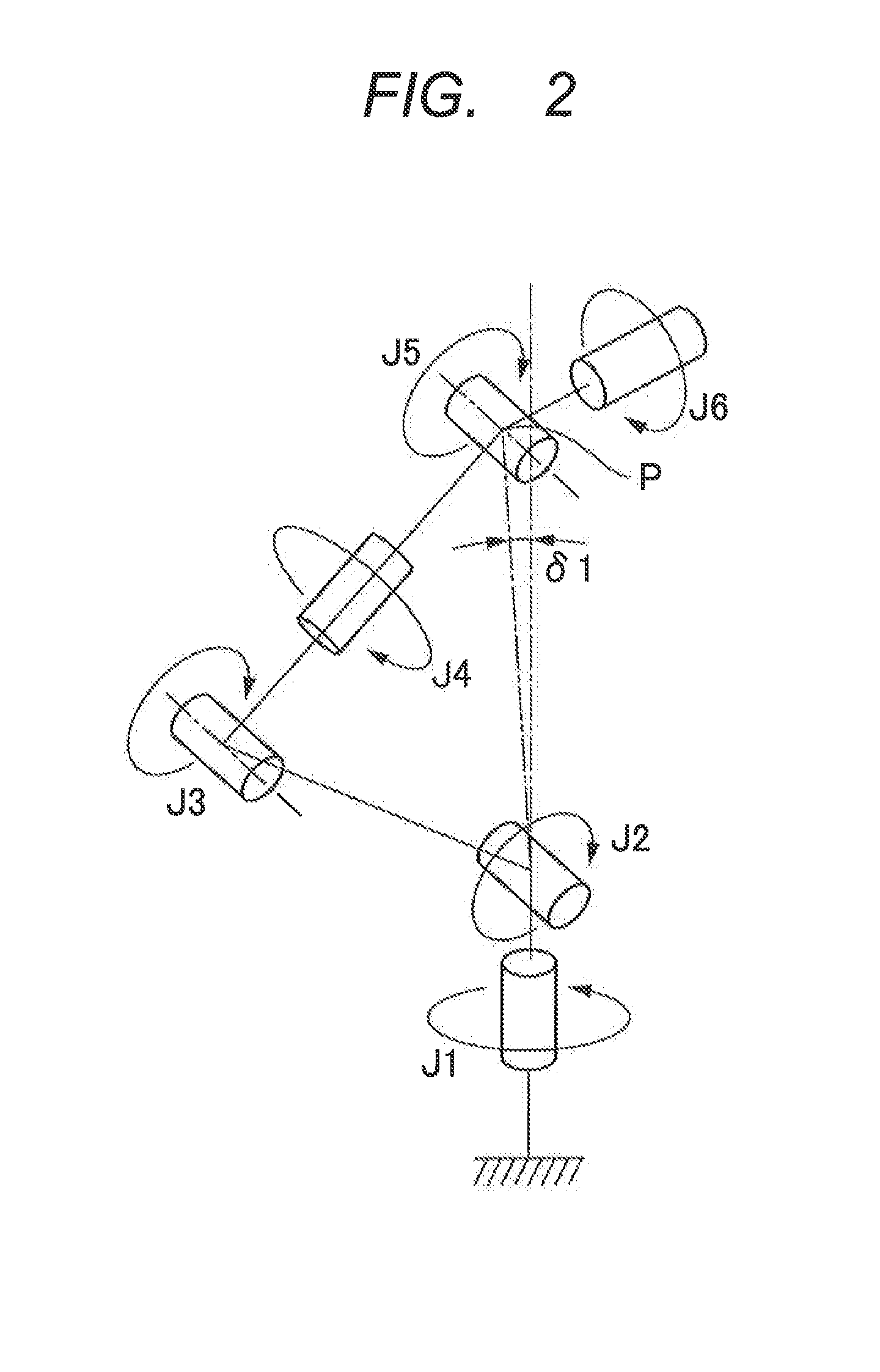
Unfortunately, a multi-articulated robot has a plurality of postures, so-called singular points, at which one position and posture designated in a three-dimensional space cannot be determined as one in a joint space, and the singular points prevent the multi-articulated robot from being intricately moved at high speed.
However, if the joint angle command speed is limited, the multi-articulated robot may significantly deviate from the original target position of the hand tip, and a return to the original target position becomes difficult once the multi-articulated robot deviates therefrom.
Unfortunately, in the technique disclosed in Japanese Patent Application Laid-Open No. 2003-300183, the joint angle speed is always limited, and hence a motion of the multi-articulated robot becomes slower at a position and a posture other than the singular point.

Method used


Image

  • Robot apparatus and robot controlling method
  • Robot apparatus and robot controlling method
  • Robot apparatus and robot controlling method

Examples


first embodiment

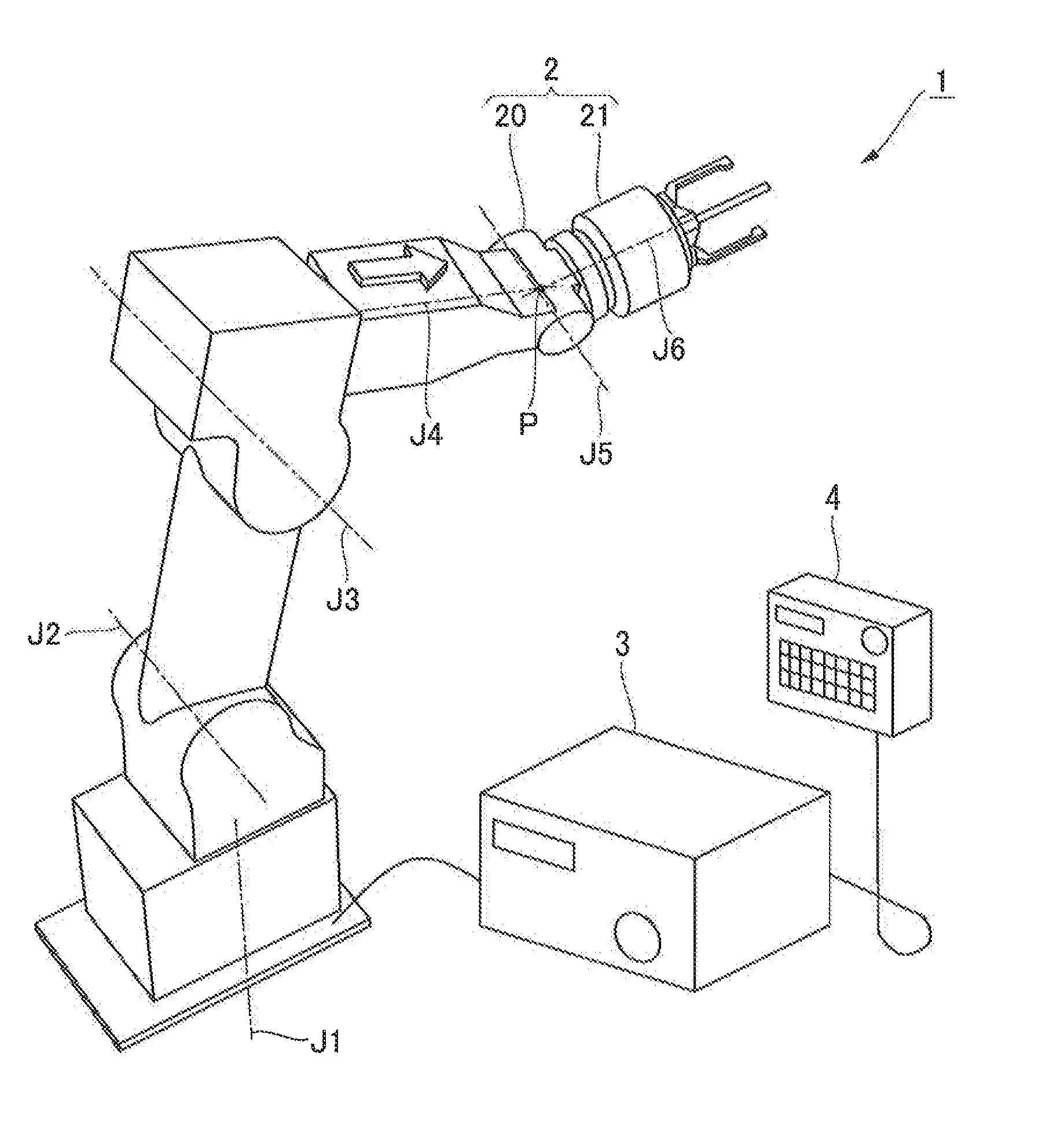
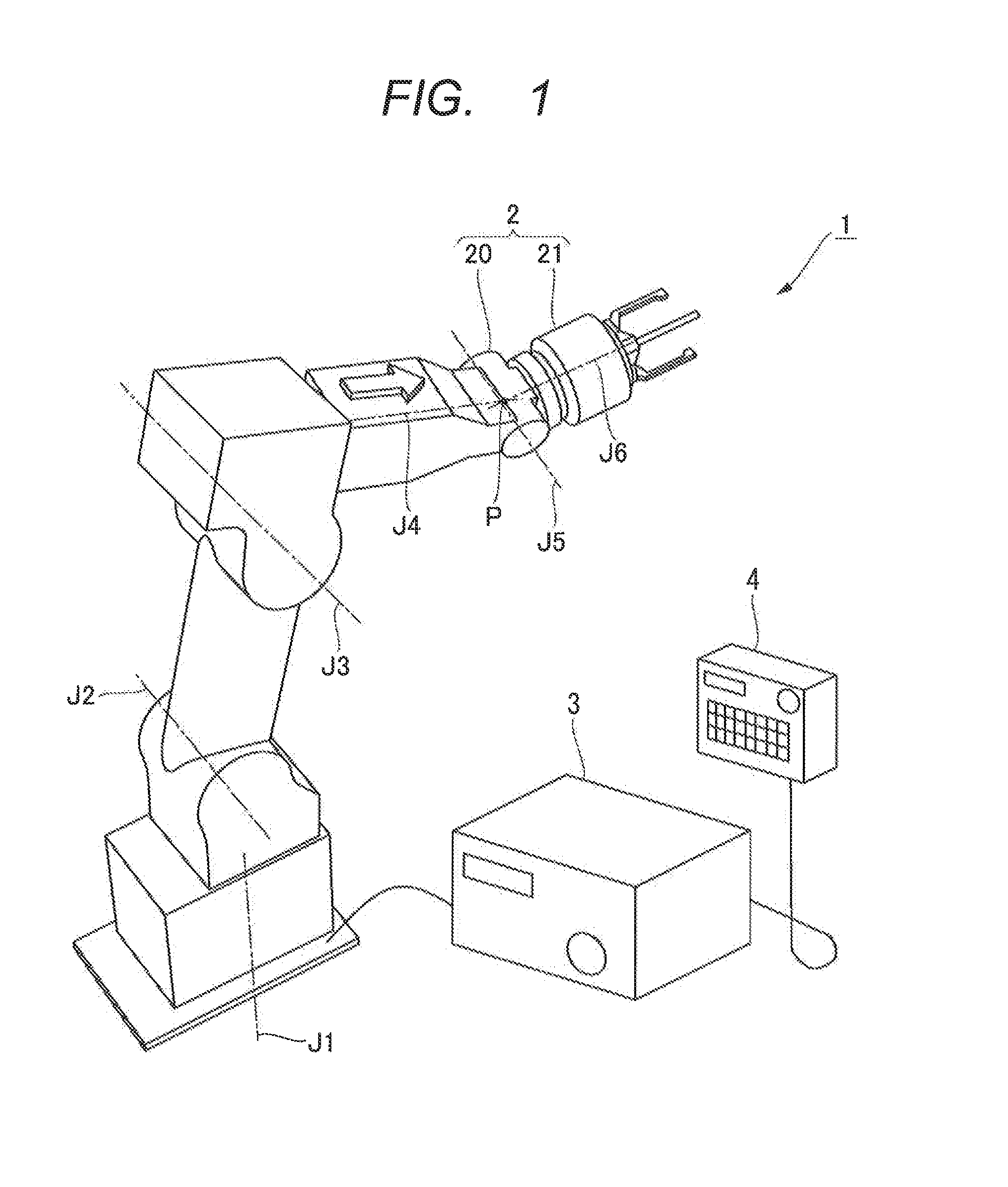
[0027]Hereinafter, a robot apparatus according to a first embodiment of the present invention is described with reference to FIG. 1 to FIG. 7. First, a schematic configuration of an entire robot apparatus 1 according to the first embodiment is described with reference to FIG. 1. FIG. 1 is a view schematically illustrating an overall structure of the robot apparatus 1 according to the first embodiment of the present invention.

[0028]As illustrated in FIG. 1, the robot apparatus 1 includes: a six-axis vertical multi-articulated robot (hereinafter, referred to as “multi-articulated robot”) 2 that performs assembling of workpieces; a controller 3 that controls the multi-articulated robot 2; and a teaching pendant 4 that can be used to operate the multi-articulated robot 2.

[0029]The multi-articulated robot (multi-articulated manipulator) 2 includes a six-axis multi-articulated robot arm 20 and an end effector 21 connected to the distal end of the robot arm 20. The robot arm 20 includes si...

second embodiment

[0068]Next, a robot apparatus according to a second embodiment is described with reference to FIG. 8. The second embodiment is different from the first embodiment in that the forward kinematics calculating unit 57 of the joint controlling apparatus 31 is replaced with a Jacobian matrix calculating unit 59 and a Jacobian matrix multiplying unit 60. Hence, in the second embodiment, the Jacobian matrix calculating unit 59 and the Jacobian matrix multiplying unit 60 are described. FIG. 8 is a block diagram illustrating a configuration of a joint controlling apparatus 31A according to the second embodiment.

[0069]In forward kinematics calculation, the position and the posture is sequentially calculated from the joint at the root, whereby the position and the posture of the hand tip is calculated. Then, it is known that the position and the posture of the hand tip can be approximately calculated by multiplication using a Jacobian matrix. The Jacobian matrix calculating unit 59 calculates s...

third embodiment

[0072]Next, a robot apparatus according to a third embodiment is described with reference to FIG. 9. The third embodiment is different from the first embodiment in that a correction amount modifying unit 61 is added to make the correction amount smaller. Hence, in the third embodiment, the correction amount modifying unit 61 is described. FIG. 9 is a block diagram illustrating a configuration of a joint controlling apparatus 31B according to the third embodiment.

[0073]Here, assumed is a scene where an operator presses a button of the teaching pendant 4 and moves the hand tip position (end effector 21) of the multi-articulated robot 2. The deviation command continues to output a number other than zero, while the button of the teaching pendant 4 is pressed. If the robot arm 20 continues to move and approaches a singular point, the hand tip speed is decreased by the speed limitations of the rotational joints, and an amount corresponding to the limited motion at this time is accumulated...


PUM


Abstract

A robot apparatus 1 includes: a multi-articulated robot 2; and a controller 3 that drive-controls the multi-articulated robot 2 based on an input motion command. The controller 3 includes: a joint angle computing unit 32 that computes each joint angle command for driving the multi-articulated robot 2 based on the motion command; a servo controlling apparatus 30 that moves the multi-articulated robot 2 by rotationally driving each rotational joint based on the joint angle command computed by the joint angle computing unit 32; a singular point calculating unit 51 that calculates a distance between the multi-articulated robot 2 and a singular point of the multi-articulated robot 2; and a maximum joint angle deviation adjusting unit 52 that limits a maximum rotation speed of a rotational joint specified in advance based on a singular point type, if the singular point distance becomes smaller than a predetermined value.

Description

BACKGROUND OF THE INVENTION[0001]1. Field of the Invention[0002]The present invention relates to a robot apparatus including a multi-articulated robot and a method for controlling a multi-articulated robot.[0003]2. Description of the Related Art[0004]In recent years, robot apparatuses that cause multi-articulated robots to perform work such as assembling of workpieces have been increasingly developed. Such robot apparatuses ultimately aim at moving the multi-articulated robots like human hands and cause the multi-articulated robots to perform work such as assembling of complicated workpieces at high speed.[0005]Unfortunately, a multi-articulated robot has a plurality of postures, so-called singular points, at which one position and posture designated in a three-dimensional space cannot be determined as one in a joint space, and the singular points prevent the multi-articulated robot from being intricately moved at high speed. Hence, it is important to appropriately process such sing...

Claims


Application Information

Patent Timeline
Patent Type & Authority Applications(United States)
IPC IPC(8): B25J9/06
CPCB25J9/06B25J9/1607G05B2219/40331G05B2219/40333G05B2219/43203
Inventor NEGISHI, MAHITO
Owner CANON KK
Learn More