Apparatus for eye contact video call

a technology for eye contact and video call, which is applied in the direction of electrical equipment, two-way working systems, television systems, etc., can solve the problems of inability to achieve real-time video calls, inability to reduce readability, and need to employ additional shutters

Active Publication Date: 2015-02-19
RES COOPERATION FOUND OF YEUNGNAM UNIV
View PDF5 Cites 30 Cited by
  • Summary
  • Abstract
  • Description
  • Claims
  • Application Information

AI Technical Summary

Benefits of technology

[0029]According to the apparatus for eye contact video call of the present disclosure configured as above, unlike a conventional apparatus for an eye contact video call, the readability is increased by forming a transparent display only at a central part of an opaque display and the manufacturing cost of the display can be reduced compared to the whole body transparent display.
[0031]Further, the camera controls on / off to be crossed with the on / off cycles of the transparent display; or selectively removes a video frame at the moment that the transparent display is on among a video photographed by the camera; or reconstructs a transmission video by selecting only a video frame photographed at the moment that the transparent display is off (transparent glass mode). Therefore, there is no need to additionally transmit and receive a synchronization signal in regards to both callers, accordingly an apparatus for detecting the synchronization signal is not necessary such that a construction and control thereof may be simple.
[0032]Furthermore, a video call system of the other party can use the conventional video call system without modification.

Problems solved by technology

However, such conventional video call apparatus has a problem in that positions of a screen and camera are not matched during a video call thus a realistic video call is impossible since eyes of another caller are not headed to his / her eyes.
However, such conventional system for eye contact image communication has a problem in that it is difficult to be used as a usual display and the manufacturing cost increases since the entire display screen is formed of a transparent display thus causing the readability to be decreased.
Further, there is another problem in that an additional shutter needs to be employed in order to open and shut the camera.
Also, a synchronous signal should be exchanged in addition to the video data thereby causing, a system constituent to be increased and also construction and control to be complex.
Further, the apparatus consists of physically separated modules and thus, the system construction may be complex unlike the existing single-body display.

Method used


Image

  • Apparatus for eye contact video call
  • Apparatus for eye contact video call
  • Apparatus for eye contact video call

Examples


Embodiment Construction

[0040]As the present disclosure allows for various changes and numerous embodiments, particular embodiments will be illustrated in the drawings and described in detail in the written description. When it is determined that detailed descriptions for well-known technologies or configurations may unnecessarily make the point of the present disclosure unclear, the detailed descriptions are not provided in explaining the present disclosure.

[0041]Reference will be now made in detail to the preferred embodiment of the present disclosure with reference to the attached drawings.

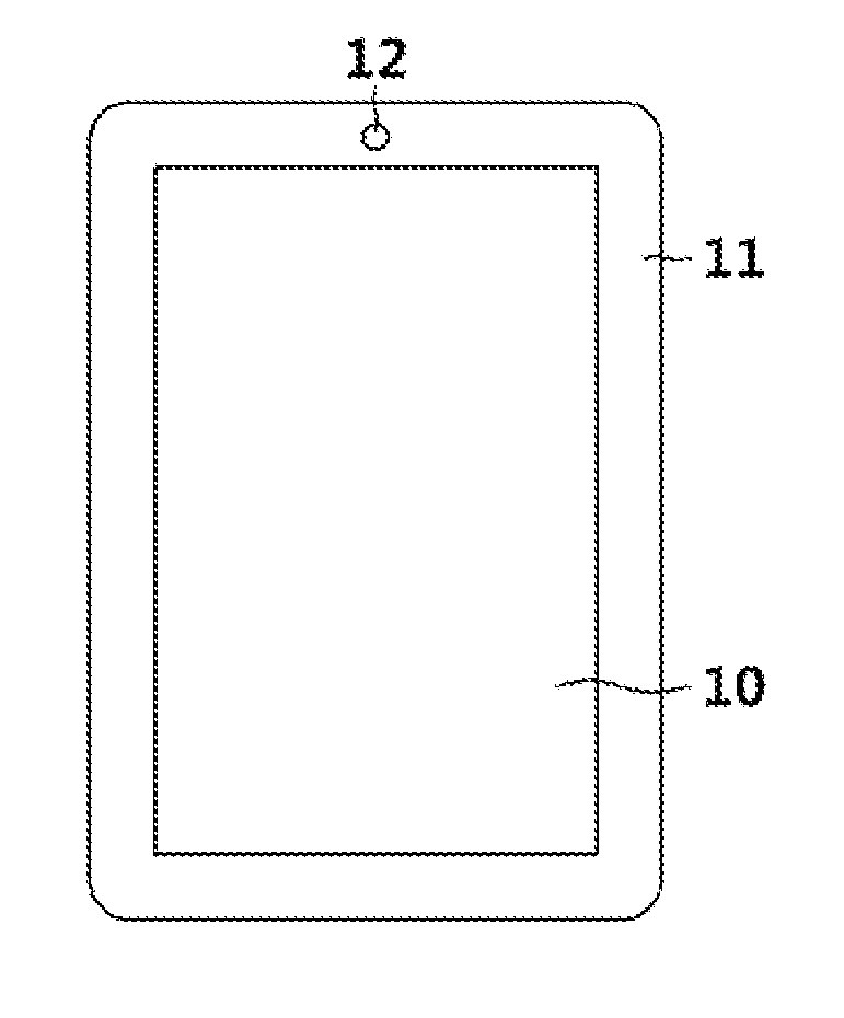
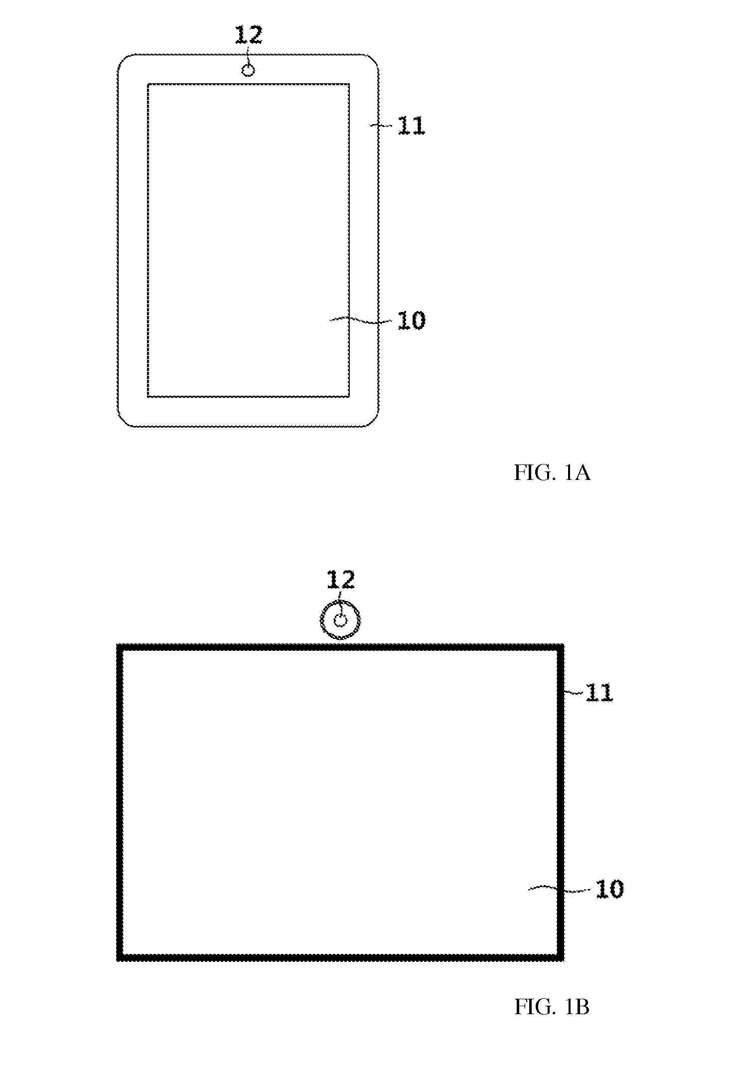
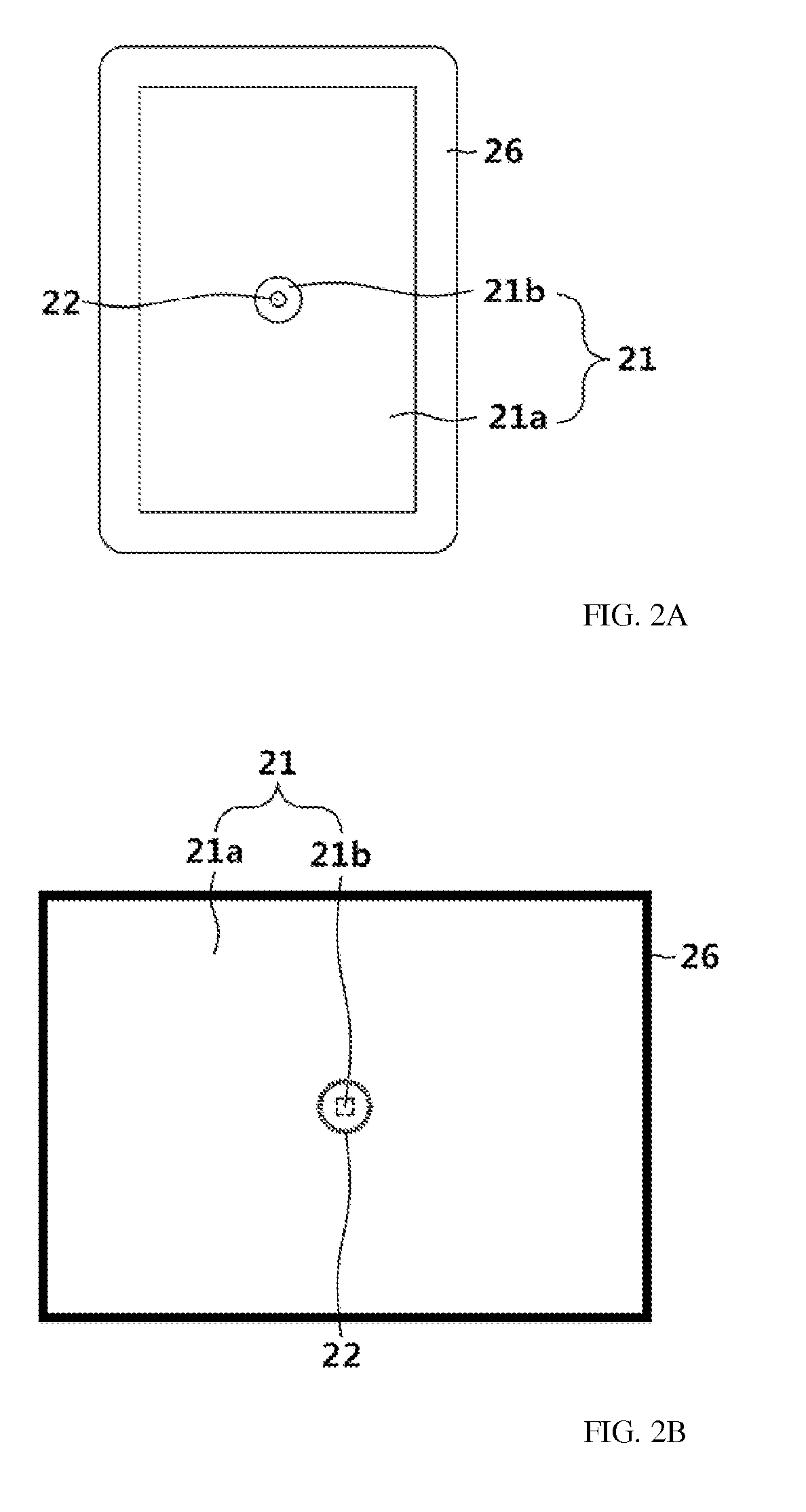
[0042]FIGS. 2A and 2B are front views illustrating an apparatus for an eye contact video call according to one exemplary embodiment of the present disclosure. FIG. 2A is a view illustrating a tablet PC in an example, FIG. 2B is a view illustrating an example of a PC screen, and FIG. 2C is a side section view of FIG. 2A. Here, the apparatus illustrated in FIGS. 2A and 2B is just an exemplary example of the present disc...


PUM


Abstract

The present disclosure relates to an apparatus for an eye contact video call capable of a realistic call in eye contact with the other party. A transparent display is formed at a central part of the opaque display and a camera is formed at a rear side thereof, thereby allowing a realistic call in eye contact with the other party and at the same time, the readability to be improved even in cases of a usual display use (mode). Further, the manufacturing cost of a terminal may be reduced and an interference of an output video of a transparent display that exists in the camera photograph video may also be effectively eliminated.

Description

CROSS-REFERENCE TO RELATED APPLICATION[0001]This application claims priority under 35 U.S.C. §119 to Korean Patent Application No. 10-2013-0097443 filed on Aug. 16, 2013, the disclosure of which is hereby incorporated by reference in its entirety.BACKGROUND[0002]1. Technical Field[0003]The present disclosure relates to an apparatus for an eye contact video call which includes not only private video calls but also industrial applications such as remote conference call, remote medical treatment and etc, and in particular, to an apparatus for an eye contact video call capable of realistically calling in cases of video call in eye contact with another party, by positioning a camera to an inside of a display concerning the IT apparatus (desktop PCs, notebook PCs, smartphones, tablet PCs, smart PCs, etc.) which uses the display.[0004]2. Description of Related Art[0005]Recent mobile terminal employs multiple cameras for use of video photograph and video call. A camera for use of video call...

Claims


Application Information

Patent Timeline
Patent Type & Authority Applications(United States)
IPC IPC(8): H04N7/14
CPCH04N7/144H04N7/14
Inventor CHOI, KWONHUE
Owner RES COOPERATION FOUND OF YEUNGNAM UNIV
Why Eureka
Try Eureka