Mechanical pencil

a technology of mechanical pencils and pencils, applied in the direction of propelling pencils, writing connectors, printing, etc., can solve the problem of bold lines, achieve the effect of reducing the number of components, improving relative position accuracy, and simplifying the cam structur

Active Publication Date: 2015-02-19
MITSUBISHI PENCIL CO LTD
View PDF13 Cites 3 Cited by
  • Summary
  • Abstract
  • Description
  • Claims
  • Application Information

AI Technical Summary

Benefits of technology

[0017]As described above, according to the mechanical pencil in accordance with the present invention, since it is arranged that the first and second fixed cams are each provided with a small number of cam faces which mesh with a part of a large number of cam faces provided at the upper and lower faces of the rotatable cam, it is possible to simplify the cam structure.
[0018]Further, since the first and second fixed cams are formed integrally with the holder member, it is possible to reduce the number of components. In addition, since the integral formation can improve the accuracy of relative positions of the first and second fixed cams, it is possible to contribute to improvement in accuracy of the meshing of the cam face and the rotatable cam.
[0019]Furthermore, since a structure is employed in which the elastic members are formed at the above-mentioned holder member to extend in the axial direction, and the above-mentioned first fixed cam and second fixed cam are formed integrally with part of the above-mentioned elastic members in the longitudinal direction. Thus, it is easy to mount the above-mentioned rotatable cam to the holder member taking advantage of the function of the above-mentioned elastic members, and the rotational drive mechanism is allowed to be easily assembled.

Problems solved by technology

As is well known, a mechanical pencil has a problem that a drawn line becomes bold, since a writing lead may locally abrade as the writing proceeds.

Method used


Image

  • Mechanical pencil
  • Mechanical pencil
  • Mechanical pencil

Examples


Embodiment Construction

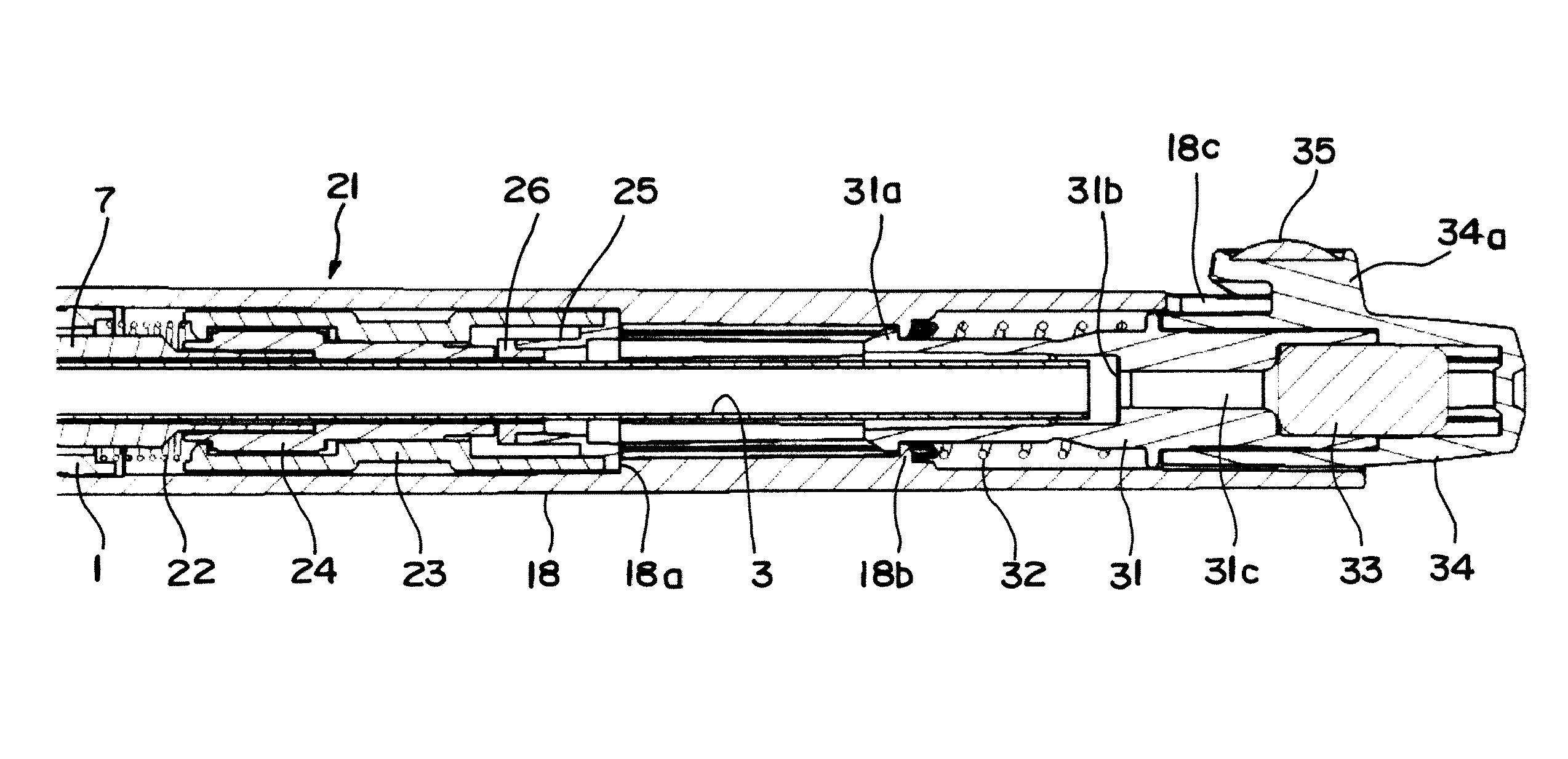
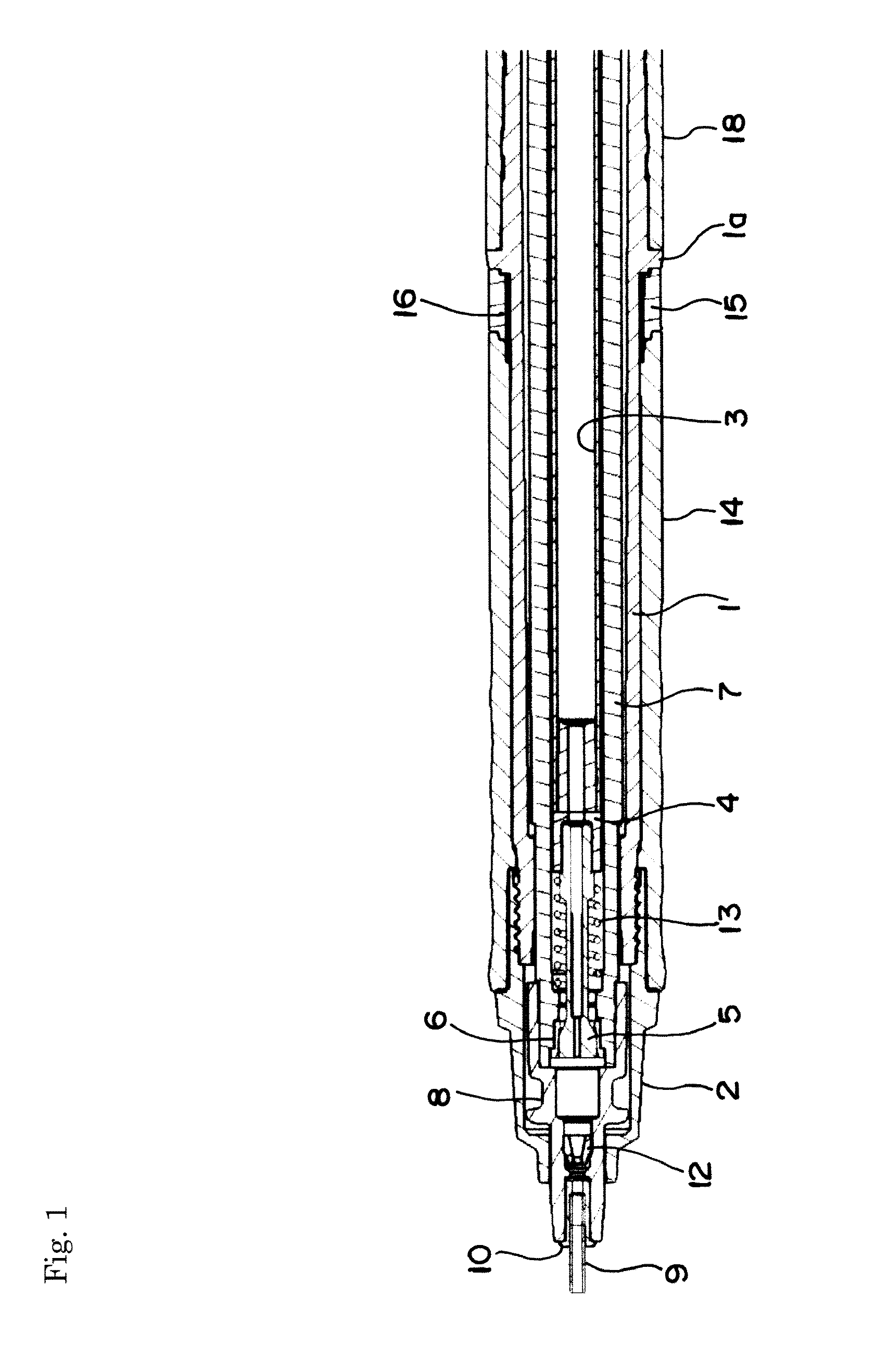
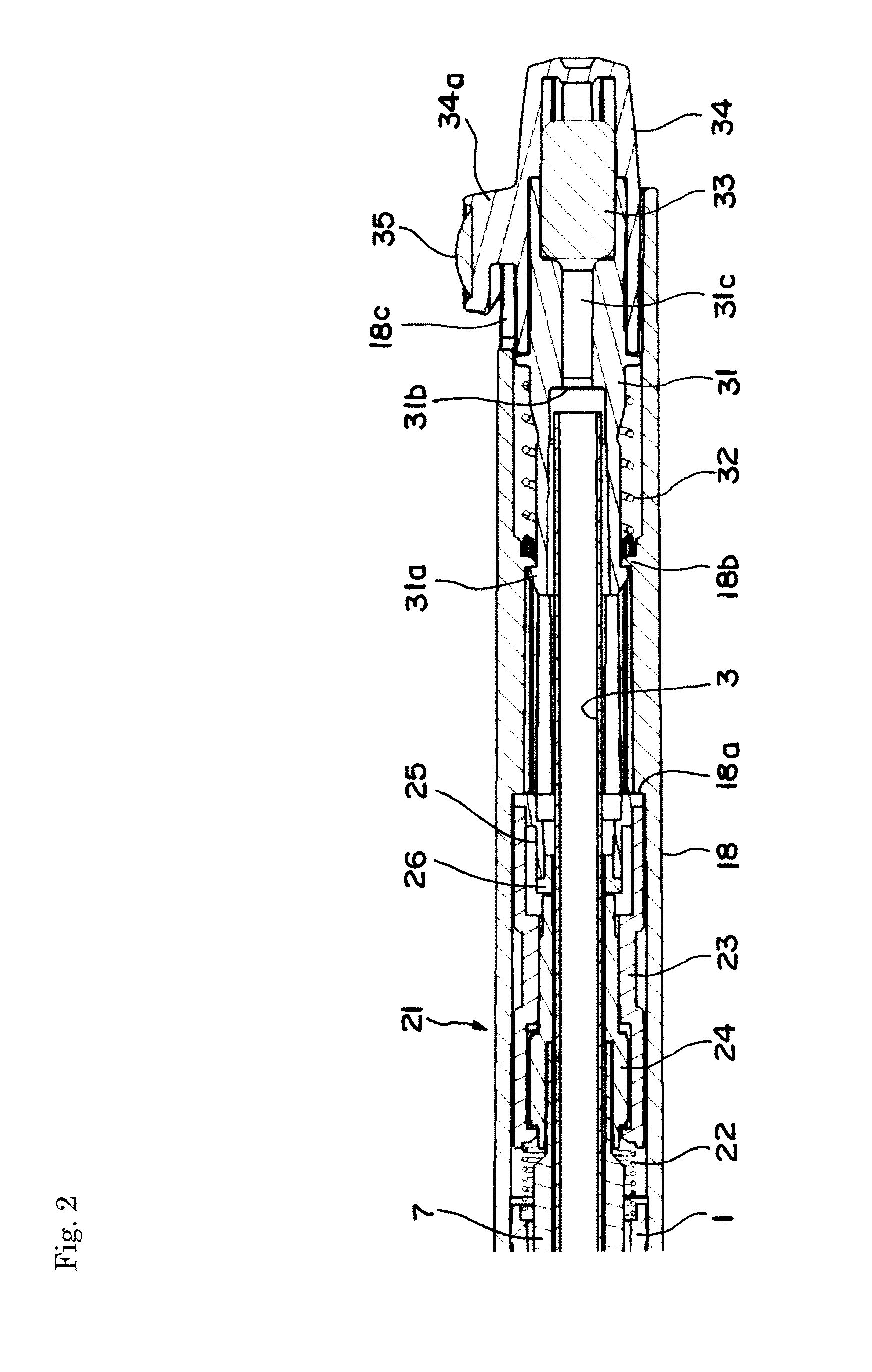
[0028]A mechanical pencil in accordance with the present invention will be described with reference to the preferred embodiment where a writing lead is rotationally driven by writing pressure. It should be noted that, in each of the drawings as illustrated below, like parts are referred to by like reference signs, but reference signs are assigned to typical parts in some drawings, and the detailed structures may be described with reference to reference signs used in other drawings for the sake of brevity.

[0029]FIGS. 1 and 2 describe the general structure of the mechanical pencil which is separated into the first half part and the second half part. Firstly in FIG. 1, a base member 2 is threadedly connected with a tip portion of a front body 1 which constitutes a body cylinder so as to be detachable from the front body 1. A cylindrical lead case 3 is accommodated along an axis of the above-mentioned front body 1 and a rear body to be described below, and a short lead case connector 4 ...


PUM


Abstract

Cam faces 24a and 24b are continuously formed in a circle on upper and lower faces which are perpendicular to an axial direction of a rotatable cam 24 which constitutes a rotational drive mechanism 21. Elastic members 23b are formed integrally with a holder member 23 for rotatably supporting the rotatable cam 24 to extend in the axial direction, and the first fixed cam and second fixed cam 23c and 23d having a small number of cam faces at butts and tips of the elastic members are arranged to face each other via the upper and lower cam faces 24a and 24b of the rotatable cam 24. The rotatable cam 24 is retreated and moved forward in the axial direction by writing pressure applied to a writing lead to be rotationally driven in one direction and rotational motion of the rotatable cam 24 is transmitted to the writing lead.

Description

TECHNICAL FIELD[0001]The present invention relates to a mechanical pencil which can rotate, for example, a writing lead (refill lead) using writing pressure, and in particular to improvement of a rotational drive mechanism for rotationally driving the writing lead etc.BACKGROUND ART[0002]As is well known, a mechanical pencil has a problem that a drawn line becomes bold, since a writing lead may locally abrade as the writing proceeds.[0003]Then, the present applicant has previously proposed a mechanical pencil provided with a rotational drive mechanism in which the writing lead is gradually rotated in one direction using writing pressure applied to the writing lead. This is disclosed in Patent Documents 1 and 2 etc.[0004]According to this mechanical pencil, in the case where a body cylinder is inclined to a writing side (page) at around 40 to 80 degrees (for example), every time a stroke is drawn, the writing lead is slightly rotationally driven in one direction, so that a tip portio...

Claims


Application Information

Patent Timeline
Patent Type & Authority Applications(United States)
IPC IPC(8): B43K21/16
CPCB43K21/16B43K21/00B43K21/006B43K21/06B43K21/22B43K23/008B43K23/02B43K29/00B43K29/02
Inventor IZAWA, HIROTAKEMORIMOTO, DAISAKU
Owner MITSUBISHI PENCIL CO LTD
Why Eureka
Try Eureka