
Components having vibration dampers enclosed therein and methods of forming such components

a technology of vibration dampers and components, applied in the field of vibration dampers, can solve the problems of mechanical components being fatigued, vibration of mechanical components may induce, and excessive localized noise in mechanical systems

Active Publication Date: 2015-02-26
GENERAL ELECTRIC CO
View PDF26 Cites 29 Cited by
  • Summary
  • Abstract
  • Description
  • Claims
  • Application Information

AI Technical Summary

Benefits of technology

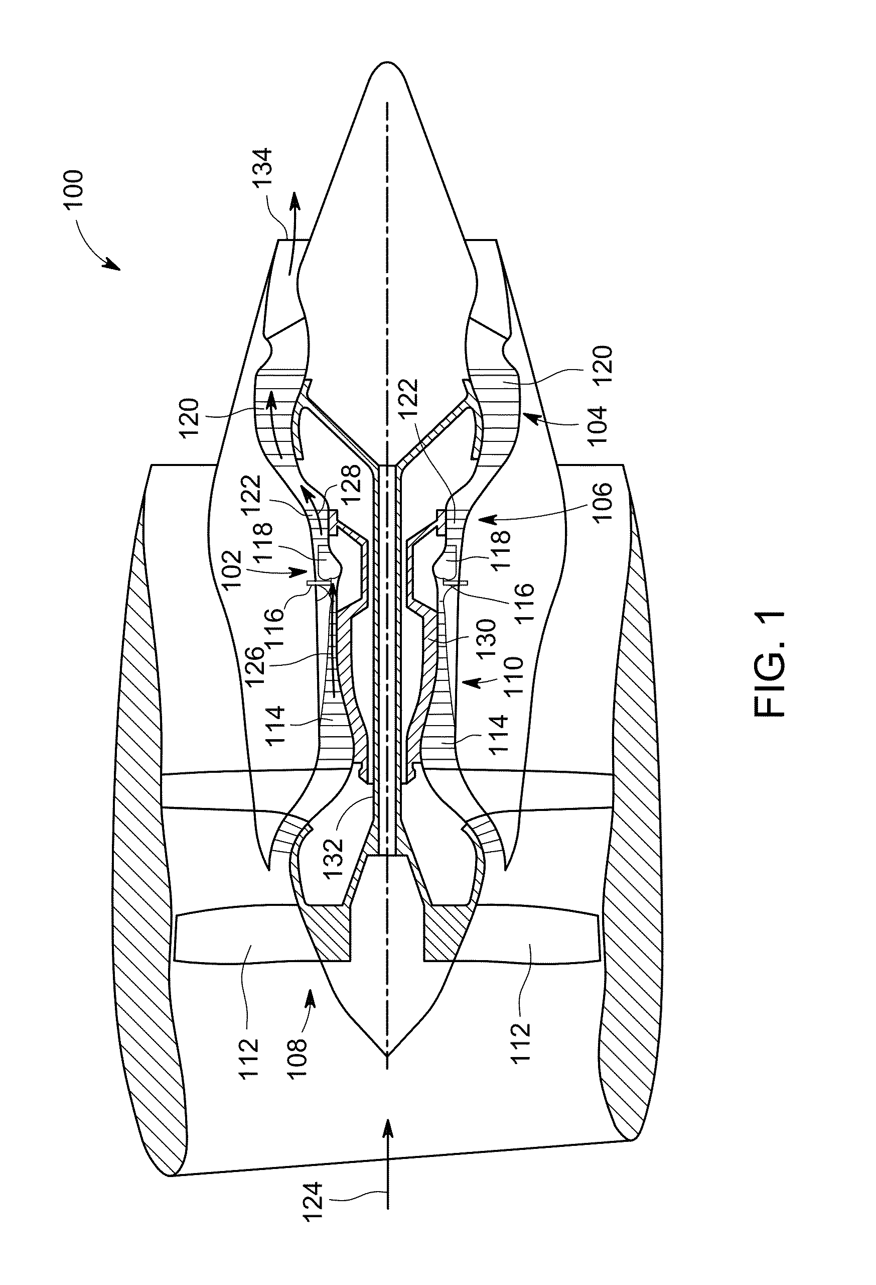
This patent describes components that can be made using an additive manufacturing process. These components have a cavity filled with a vibration reducer, which is made up of a solidified material and a flowable medium. This vibration reducer helps reduce vibrations and improve the performance of the components. The patent also describes the use of these components in gas turbine engines, where they can be used to improve the functioning of the engine. Overall, this patent provides a way to make components with improved vibration reduction using additive manufacturing techniques.

Problems solved by technology

Vibration of mechanical components may induce component fatigue and excessive localized noise within mechanical systems, such as gas turbine engines.
However, such known particle-filled cavities incorporated into mechanical components generally do not reduce vibrational loading of such components to a satisfactory level.
Further, because the cavities must be accessible after the component is formed in order to evacuate and re-fill the cavities, the locations at which particle-filled cavities may be formed within mechanical components are limited.

Method used


Image

  • Components having vibration dampers enclosed therein and methods of forming such components
  • Components having vibration dampers enclosed therein and methods of forming such components
  • Components having vibration dampers enclosed therein and methods of forming such components

Examples


Embodiment Construction

[0014]In the following specification and the claims, reference will be made to a number of terms, which shall be defined to have the following meanings.

[0015]The singular forms “a”, “an”, and “the” include plural references unless the context clearly dictates otherwise.

[0016]Approximating language, as used herein throughout the specification and claims, may be applied to modify any quantitative representation that could permissibly vary without resulting in a change in the basic function to which it is related. Accordingly, a value modified by a term or terms, such as “about” and “substantially”, are not to be limited to the precise value specified. In at least some instances, the approximating language may correspond to the precision of an instrument for measuring the value. Here and throughout the specification and claims, range limitations may be combined and / or interchanged, such ranges are identified and include all the sub-ranges contained therein unless context or language in...


PUM

PropertyMeasurementUnit
Fractionaaaaaaaaaa
Flow rateaaaaaaaaaa
Volumeaaaaaaaaaa

Abstract

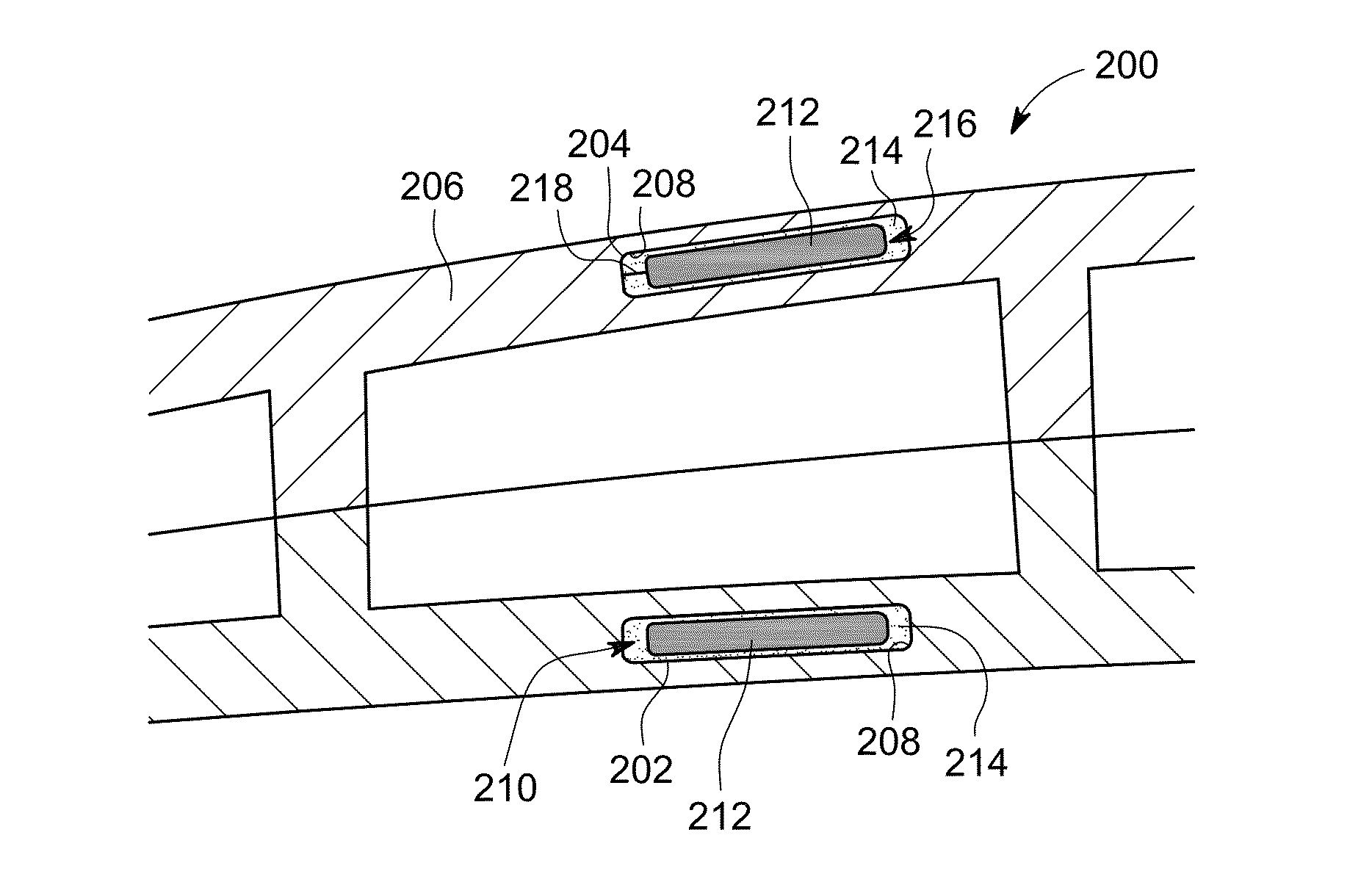
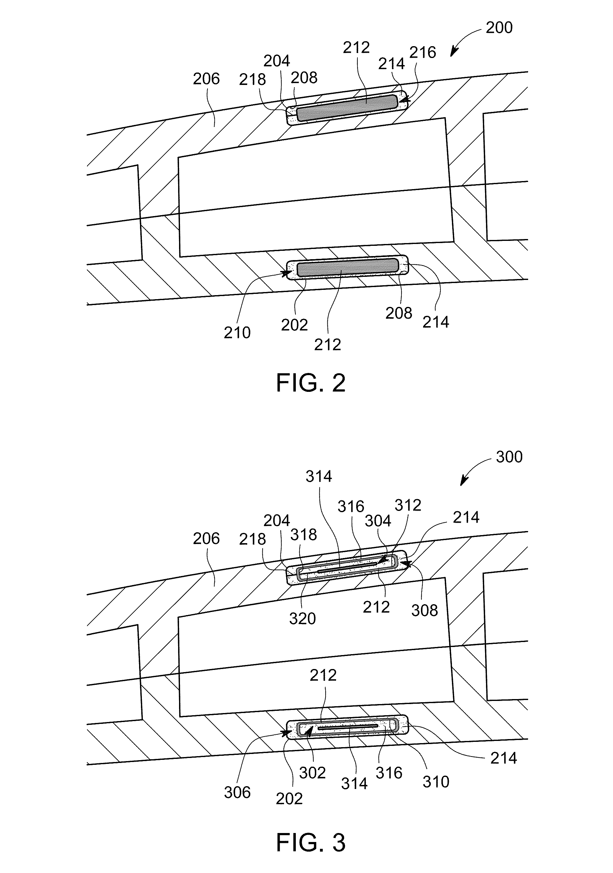
A component formed by an additive manufacturing process includes a body and a first vibration damper. The body is formed from an additive manufacturing material, and defines at least a first cavity completely enclosed within the body. The first vibration damper is disposed within the first cavity. The first vibration damper includes a flowable medium and a first solidified element formed from the additive manufacturing material. The flowable medium surrounds the first solidified element.

Description

BACKGROUND[0001]The field of the disclosure relates generally to vibration dampers and, more particularly, to components having vibration dampers enclosed therein, and methods of forming such components.[0002]Vibration of mechanical components may induce component fatigue and excessive localized noise within mechanical systems, such as gas turbine engines. Accordingly, reducing vibrational loading of mechanical components within such mechanical systems is a priority among producers and users of such systems.[0003]At least some known attempts to reduce vibrational loading of mechanical components include incorporating particle-filled cavities within the mechanical components.[0004]However, such known particle-filled cavities incorporated into mechanical components generally do not reduce vibrational loading of such components to a satisfactory level. Moreover, fabrication of such components generally requires separate steps for forming the cavities, evacuating the cavities, and re-fi...

Claims


Application Information

Patent Timeline
IPC IPC(8): F16F9/10F16F9/30B29C67/00F02C3/04B22F3/105B22F7/06
CPCF16F9/10B22F3/1055B22F7/06B29C67/0074F02C3/04F05D2260/96B29K2101/10B29K2101/12B33Y10/00B33Y80/00F05D2230/30F16F9/30B22F5/009F01D5/16F16F15/366F05D2230/31B22F5/04Y10T428/24612Y02P10/25B22F10/28B22F10/66B22F10/40B22F10/00F01D25/06F05D2220/36
Inventor ERNO, DANIEL JASONHEDEEN, ROBERT ARVINSINGH, PRABHJOT
Owner GENERAL ELECTRIC CO
Learn More