Receiver for wireless charging system

a wireless charging and receiver technology, applied in the direction of inductance, loop antennas with ferromagnetic cores, transportation and packaging, etc., can solve the problems of user trouble, terminal jack or terminal damage, and user considerable inconvenience, so as to enhance the efficiency of magnetic field and enhance reception efficiency

Active Publication Date: 2015-02-26
SAMSUNG ELECTRONICS CO LTD
View PDF2 Cites 137 Cited by
  • Summary
  • Abstract
  • Description
  • Claims
  • Application Information

AI Technical Summary

Benefits of technology

[0028]According to aspects of the present invention, the shape of a coil in the reception unit is effectively designed in a wireless power system and, additionally, a structure capable of enhancing efficiency of magnetic fields of the r

Problems solved by technology

However, since charging is still accomplished through a long cable wired between a charger and a device, users considerably suffer from troubles and inconvenience due to the limitation on distance.
In addition, when a plurality of terminals is charged using one charger, there is a problem in that the users can be troubled due to manual attachment and detachment of the charger and the terminal jack or the terminal can be damaged due to abrasion or damages of a connection part.
However, since the specification and shape of a terminal are different among devices in a connection terminal type, users suffer from difficulties of repeatedly purchasing a new charging device, and this method generates a new problem of discarding previously used chargers when a new device is purchased.
However, when the non-contact type charging method is applied to a cellular phone or a smart phone, needless to say that the variation should be improved, there is a problem in that since various types of wireless chargers are released in a predetermined method,

Method used


Image

  • Receiver for wireless charging system
  • Receiver for wireless charging system
  • Receiver for wireless charging system

Examples


embodiment 1

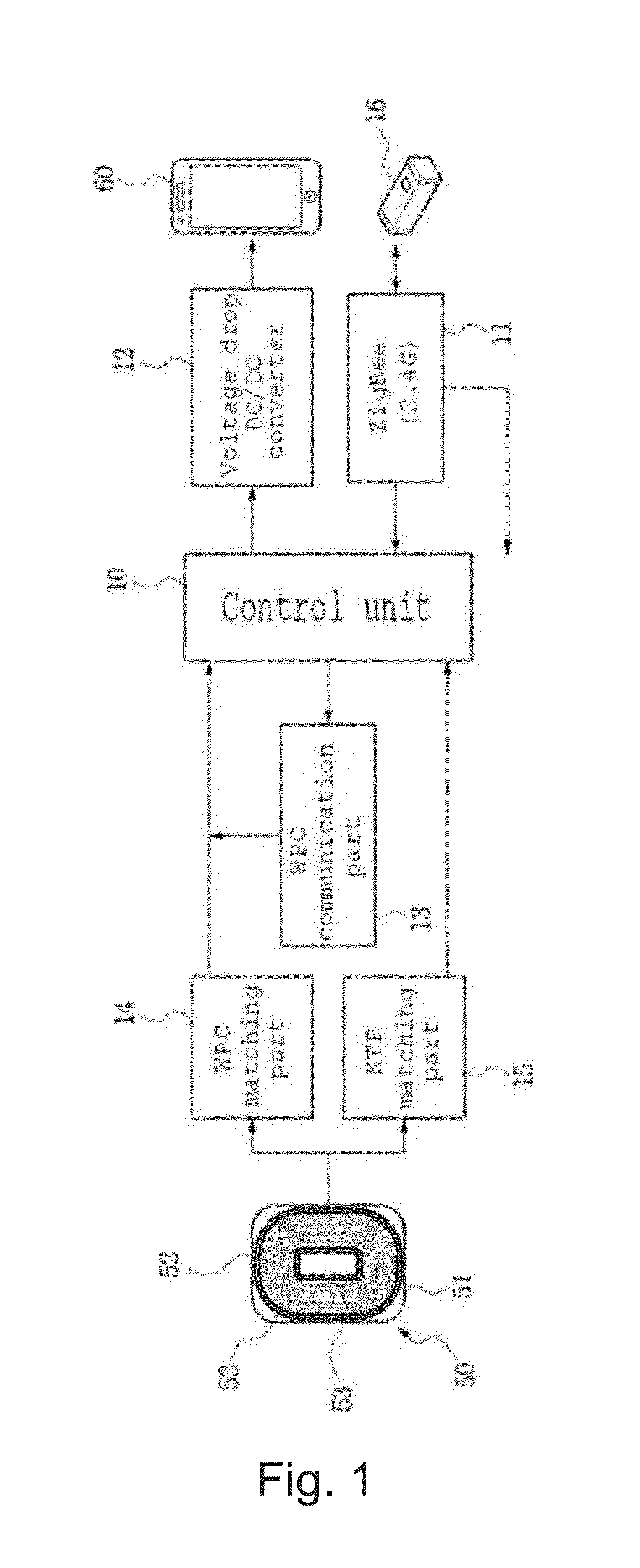
[0047]FIG. 1 is a block diagram showing a reception unit of a wireless charging system of the present invention.

[0048]Generally, a wireless charging system is configured of a transmission unit for transmitting power energy and a reception unit for receiving the power energy, and the transmission unit periodically drives a sensor to sense a predetermined signal and determines whether or not a charge request signal is sensed. When a charge request signal is sensed, a power transmission unit of the transmission unit is turned on. Then, the transmission unit confirms battery voltage of the receiving side through a signal of the reception unit, and if a charge enable state is confirmed, transmission of power is performed.

[0049]At this point, if the wireless charging system enters into the above state, the reception unit receives the power energy, and power is charged into the battery of the reception unit. That is, the block diagram of FIG. 1 shows an effective design structure of the re...

embodiment 2

[0070]FIG. 8 is a view illustrating the principle of a wireless charger.

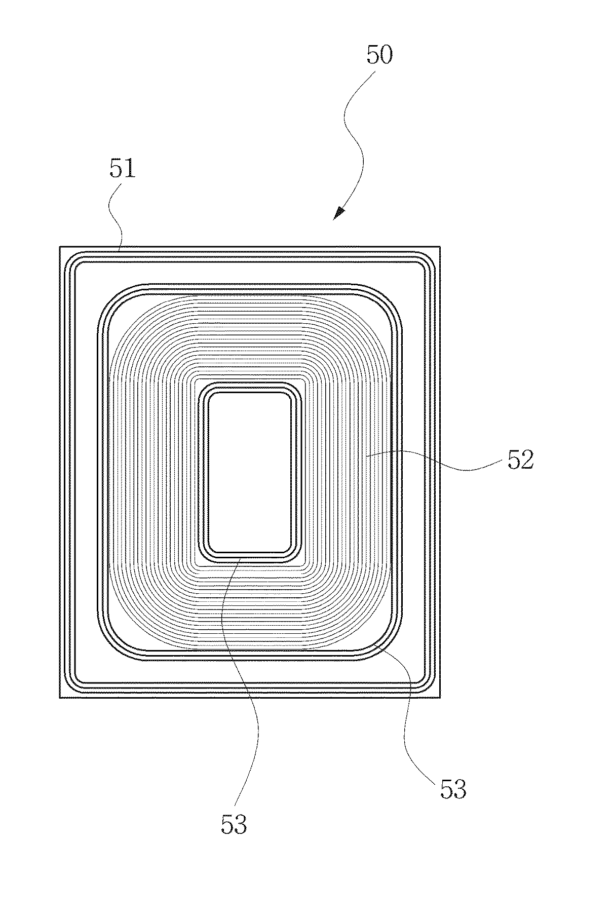
[0071]FIG. 8 shows a general structure of a wireless charger for supplying power energy. First, a reception unit 200 has a structure of connecting the antenna loop coils 52 and 53 to a condenser C in series, and a transmission unit 300 also has a structure of connecting an antenna loop coil 31 to a condenser C in parallel. The only difference is that the transmission unit 300 is further provided with a resonance filter, and the resonance filter is configured as a structure of connecting the coil 62 and the condenser C in series. At this point, it is apparent that the series and parallel connections of the loop coils and the condensers can be changed.

[0072]A method generally used in a wireless charger is a wireless power consortium (WPC) method, and the WPC method generally has following conditions in order to transfer wireless power energy.

[0073]“Voltage: 7 to 15V (in the case of the reception unit), Frequency: ...

embodiment 3

[0084]FIGS. 9 and 10 are flowcharts illustrating the present invention.

[0085]First, FIG. 9 will be described. A wireless charging system is configured of a transmission unit for transmitting power energy and a reception unit for receiving the power energy. If the reception unit transmits a signal requesting transmission of power energy to the transmission unit, the transmission unit which periodically drives a sensor to receive a predetermined signal receives a charge request signal and transmits a charging signal to the reception unit. That is, the signal received by the reception unit through a near field communication module 16 in this general procedure is transmitted to the control unit 10, and the control unit 10 exchanges signals with the transmission unit in a predetermined method (steps 150 and 152).

[0086]Then, after exchanging the communication signals with each other in a predetermined method, the reception unit receives power energy (step 153). At this point, the present ...


PUM


Abstract

A receiver for a wireless charging system, capable of receiving power energy using non-contact type magnetic induction, includes a coil capable of receiving the power energy and a part for generating a predetermined output power from the power energy received by the coil, a portable terminal, an NFC coil further provided outside of the coil, and a ferrite sheet further provided at the coil and the NFC coil.

Description

BACKGROUND OF THE INVENTION[0001]1. Field of the Invention[0002]The present invention relates to a wireless charger, and more specifically, to a receiver for a wireless charging system, which provides a new design structure for efficiently receiving power wirelessly transmitted from the wireless charger.[0003]2. Background of the Related Art[0004]Techniques of providing wireless transmission and reception units in an electronic device and accomplishing wirelessly charge are under development. Mobile communication terminals are developed in a variety of forms recently, and therefore, there are charging jacks as diverse as various forms of power chargers. Although a problem of compatibility between the chargers arises accordingly, since the charging jacks are standardized to a 24-pin charging jack, the problem of compatibility between the chargers has been solved for users.[0005]However, since charging is still accomplished through a long cable wired between a charger and a device, us...

Claims


Application Information

Patent Timeline
IPC IPC(8): H02J7/02H02J7/00H01F27/28
CPCH02J7/025H02J7/0042H01F27/2804H02J5/005H01F38/14H01F2038/143H02J50/10H02J50/005H02J50/70H02J50/80H04B5/0031H04B5/0037H02J50/402H01F27/02H01F27/245H01F27/2828H01Q1/38H01Q7/06H04B1/3833H04M1/0277H04M1/03H02J2310/22H02J50/12H02J7/0044H04M1/026
Inventor KIM, SI-HANNA, GI-YONG
Owner SAMSUNG ELECTRONICS CO LTD
Why Eureka
Try Eureka