Magnet holding structure of auto-focus module

a technology of auto-focus module and magnetic holding structure, which is applied in the direction of mountings, optics, instruments, etc., can solve the problem that more power must be consumed to drive the miniaturized auto-focus module, and achieve the effect of enhancing the magnetic field efficiency, power saving, and increasing the driving force of the electromagnetic field

Active Publication Date: 2013-05-28
TDK TAIWAN
View PDF1 Cites 0 Cited by
  • Summary
  • Abstract
  • Description
  • Claims
  • Application Information

AI Technical Summary

Benefits of technology

[0006]A primary object of the present invention is to provide a magnet holding structure of auto-focus module for enhancing the magnetic field efficiency at the corners of the winding, so as to increase the driving force of the electromagnetic field produced by the excited winding and achieve the purpose of power saving.
[0007]To achieve the above and other objects, the magnet holding structure of auto-focus module according to a preferred embodiment of the present invention includes an outer frame for holding four magnets to four inner wall surfaces of the outer frame; a lens holder for holding a lens thereto and being assembled to the outer frame via at least one spring member; and a winding mounted around the lens holder for driving the lens holder to axially move forward or rearward to focus automatically. The outer frame is provided at each of four inner corners with an inverted L-shaped plate extending downward from a top of the outer frame to locate between the lens holder and the winding, so as to face toward four spaces respectively existing between two adjacent magnets outside the winding. With these arrangements, the electromagnetic field produced by the excited winding can have enhanced magnetic efficiency at the corners of the winding.

Problems solved by technology

This means more power must be consumed to drive the miniaturized auto-focus module.

Method used


Image

  • Magnet holding structure of auto-focus module
  • Magnet holding structure of auto-focus module
  • Magnet holding structure of auto-focus module

Examples


Embodiment Construction

[0013]The present invention will now be described with a preferred embodiment thereof and with reference to the accompanying drawings. It is understood the accompanying drawings are illustrated only for assisting in describing the present invention and not intended to limit the present invention.

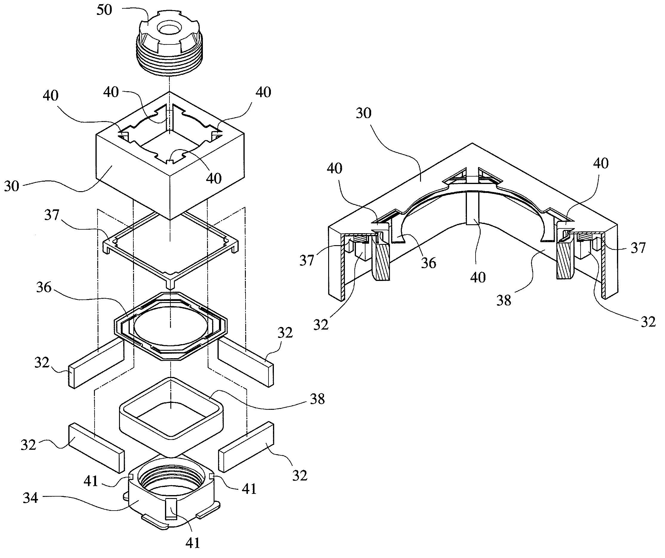
[0014]Please refer to FIG. 3 that is an exploded perspective view showing a preferred embodiment of the present invention and to FIG. 4 that is an assembled sectional perspective view of part of the elements shown in FIG. 3. As shown, an auto-focus module according to the present invention includes an outer frame 30, four magnets 32, a lens holder 34, at least one spring member 36, a spacer 37, and a winding 38. The outer frame 30 is a square member made of a metal material, and the four magnets 32 are mounted to four inner wall surfaces of the outer frame 30. The lens holder 34 internally defines an axially extended hole for a lens 50 to mount therein, and is assembled to and located in the...


PUM


Abstract

A magnet holding structure of auto-focus module includes an outer frame for holding four magnets to four inner wall surfaces of the outer frame; a lens holder for holding a lens thereto and being assembled to the outer frame via at least one spring member; and a winding fitted around the lens holder for driving the lens holder to axially move forward or rearward to focus automatically. The outer frame is provided at each of four inner corners with an inverted L-shaped plate extending downward from a top of the outer frame to locate between the lens holder and the winding, so as to face toward four spaces respectively existing between two adjacent magnets outside the winding. With these arrangements, the electromagnetic field produced by the winding can have enhanced magnetic efficiency and increased driving force at the corners of the winding to achieve the purpose of power saving.

Description

FIELD OF THE INVENTION[0001]The present invention relates to a magnet holding structure of auto-focus module, and more particularly to a structure in a miniature lens auto-focus module to enable enhanced magnetic induction efficiency on the winding.BACKGROUND OF THE INVENTION[0002]With the progress in scientific technologies as well as the modularization and miniaturization of camera lens, it is now possible to produce digital cameras having a very small volume, and most of currently available mobile phones are provided with the function of a digital camera. There are various types of auto-focus driving structures for the conventional miniature lens. Among others, the voice coil motor (VCM) is the currently most widely employed auto-focus driving structure. This is because the VCM has the advantages of small volume, low power consumption, accurately actuated displacement, and cost-effective, and is therefore very suitable for short-distance driving in miniature lens auto-focusing.[0...

Claims


Application Information

Patent Timeline
Patent Type & Authority Patents(United States)
IPC IPC(8): G02B15/14
CPCG02B7/08
Inventor WU, FU-YUANHSU, SHANG-YU
Owner TDK TAIWAN
Why Eureka
Try Eureka