
Composite pylon for a prosthetic device

a prosthetic device and composite technology, applied in the field of prosthetic legs, can solve the problems of increasing the weight of the prosthesis, adding bulk and additional weight to the prosthesis, and conventional prostheses can become uncomfortabl

Inactive Publication Date: 2015-03-12
WILSON MICHAEL THOMAS
View PDF13 Cites 4 Cited by
  • Summary
  • Abstract
  • Description
  • Claims
  • Application Information

AI Technical Summary

Benefits of technology

The patent describes a new design for a pylon, which is a component of a prosthetic device. The pylon has a central axis and connects a socket for an amputee to a prosthetic foot. It is made up of a first connecting member at one end, a second connecting member at the other end, and a pylon member that extends between the two connectors. The pylon member is designed to extend helically or spirally around the central axis. The patent also describes a pylon adapter that can connect to different pylons for different users. The technical effects of this design may include improved stability, comfort, and more natural movement for prosthetic users.

Problems solved by technology

However, inclusion of a prosthetic ankle may add bulk and additional weight to the prosthesis.
However, similar to prosthetic ankles, inclusion of such energy-storing components may significantly increase the weight of the prosthesis.
Although some conventional prosthetics are sufficiently strong and durable to withstand the stresses of repeated stepping motions over long periods of time, some conventional prostheses can become uncomfortable after extended periods of use due to excessive weight, bulkinesss, and inherent inflexibility of many of the components making up the prosthetic.
Such discomfort may discourage use of the prosthetic and thus results in a reduced quality of life for the patient.

Method used


Image

  • Composite pylon for a prosthetic device
  • Composite pylon for a prosthetic device
  • Composite pylon for a prosthetic device

Examples


Embodiment Construction

[0021]The following discussion is directed to various exemplary embodiments. However, one skilled in the art will understand that the examples disclosed herein have broad application, and that the discussion of any embodiment is meant only to be exemplary of that embodiment, and not intended to suggest that the scope of the disclosure, including the claims, is limited to that embodiment.

[0022]Certain terms are used throughout the following description and claims to refer to particular features or components. As one skilled in the art will appreciate, different persons may refer to the same feature or component by different names. This document does not intend to distinguish between components or features that differ in name but not function. The drawing figures are not necessarily to scale. Certain features and components herein may be shown exaggerated in scale or in somewhat schematic form and some details of conventional elements may not be shown in interest of clarity and concis...


PUM


Abstract

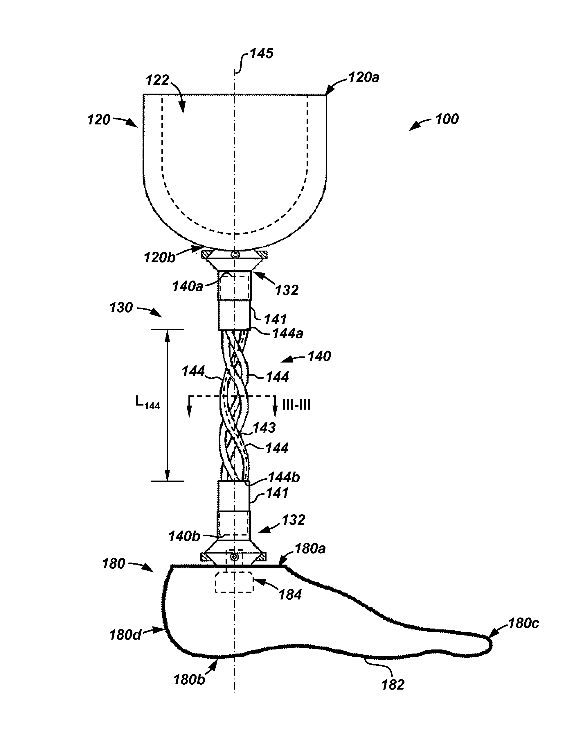
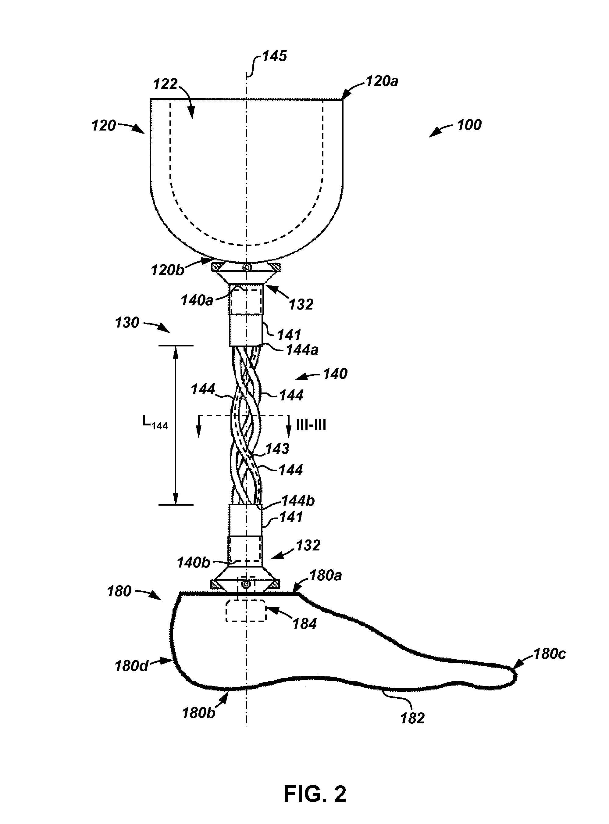
A pylon for a prosthetic device, the pylon having a central axis, a first end, and a second end. In an embodiment, the pylon includes a first connecting member disposed at the first end and configured to couple to a socket worn by an amputee. In addition, the pylon includes a second connecting member disposed at the second end and configured to couple to a prosthetic foot. Further, the pylon includes a pylon member extending axially from the first connecting member to the second connecting member, wherein the pylon member extends helically about the central axis.

Description

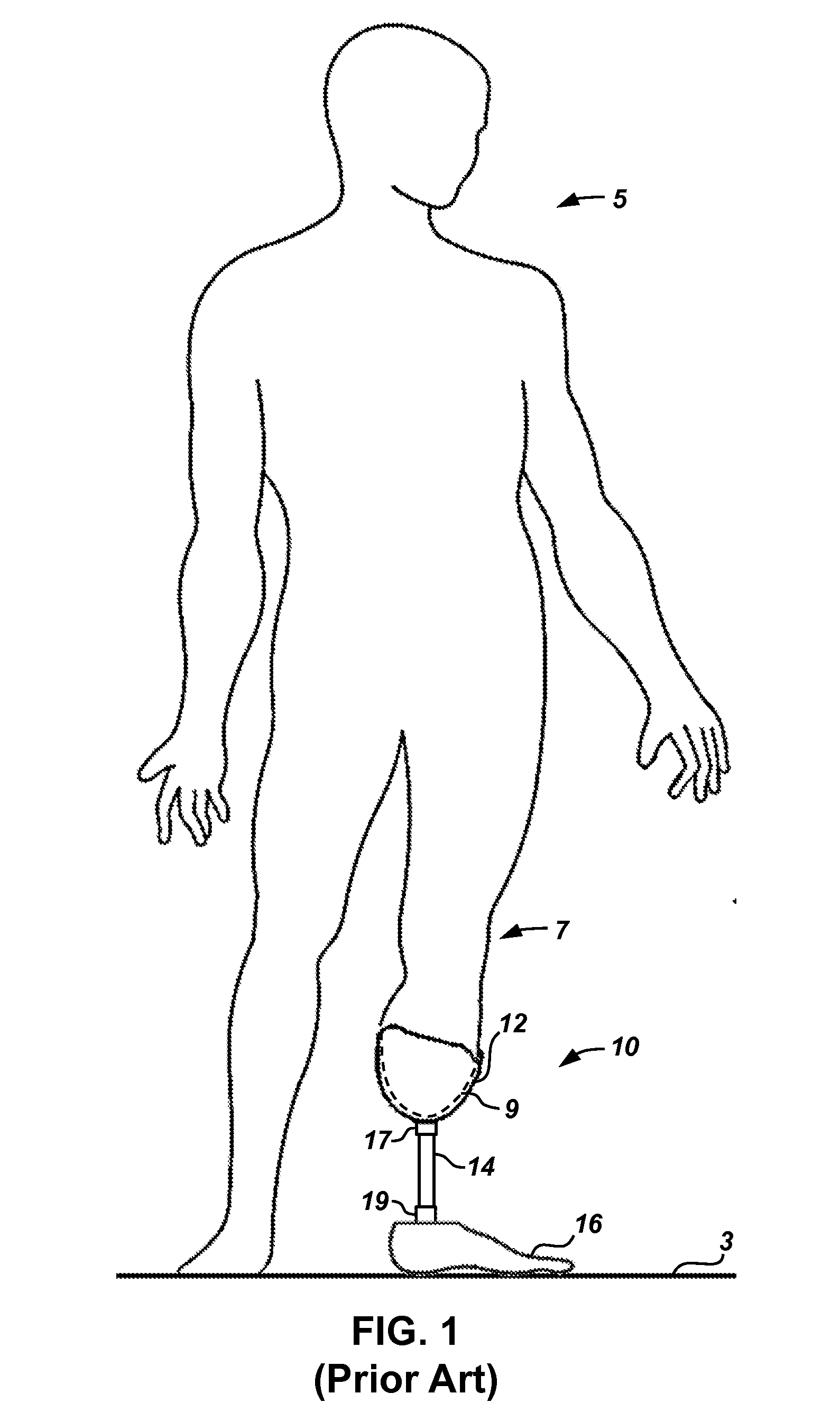
CROSS-REFERENCE TO RELATED APPLICATIONS[0001]This application claims benefit of U.S. provisional patent application Ser. No. 61 / 876,272 filed Sep. 11, 2013, and entitled “Composite Pylon for a Prosthetic Device,” which is hereby incorporated herein by reference in its entirety.STATEMENT REGARDING FEDERALLY SPONSORED RESEARCH OR DEVELOPMENT[0002]Not applicable.BACKGROUND[0003]Embodiments disclosed herein relate generally to prosthetic limbs. More particularly, embodiments disclosed herein relate to flexible pylons for coupling prosthetic extremities to amputees.[0004]Amputees typically employ the use of prosthetic limbs to replace the function of the particular limb that is missing. For patients who have had one of their legs amputated at or below the knee, the prosthesis typically includes a prosthetic foot, a socket within which the post-operative stump or residual limb is seated, and a rigid pylon extending between the socket and the prosthetic foot.[0005]A useful prosthesis at le...

Claims


Application Information

Patent Timeline
Patent Type & Authority Applications(United States)
IPC IPC(8): A61F2/78A61F2/80
CPCA61F2/80A61F2/7812A61F2/60A61F2002/607
Inventor WILSON, MICHAEL THOMAS
Owner WILSON MICHAEL THOMAS
Learn More