Rotary union

a technology of rotary unions and rotary joints, applied in the direction of pipe joints, adjustment joints, printing, etc., can solve the problems of air bubbles introducing difficulties in high rotational speed operations, unfavorable flow rate, and partial blockage within

Active Publication Date: 2015-04-02
THE PROCTER & GAMBLE COMPANY
View PDF5 Cites 16 Cited by
  • Summary
  • Abstract
  • Description
  • Claims
  • Application Information

AI Technical Summary

Problems solved by technology

These gas or air bubbles introduce difficulties in high rotational speed operations, such as printing and coating.
These can include undesirable flowrates, partial blockages within the internal roll piping, noise, vibration, and damage to the piping network.

Method used


Image

  • Rotary union
  • Rotary union
  • Rotary union

Examples


Embodiment Construction

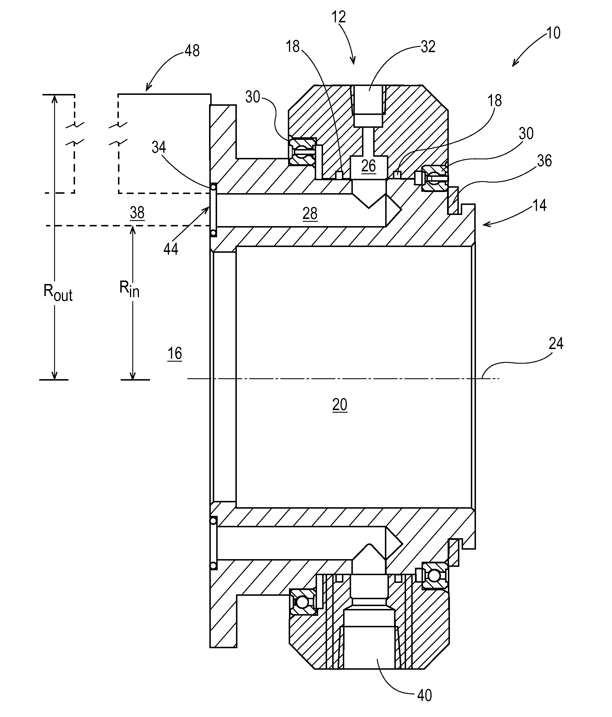
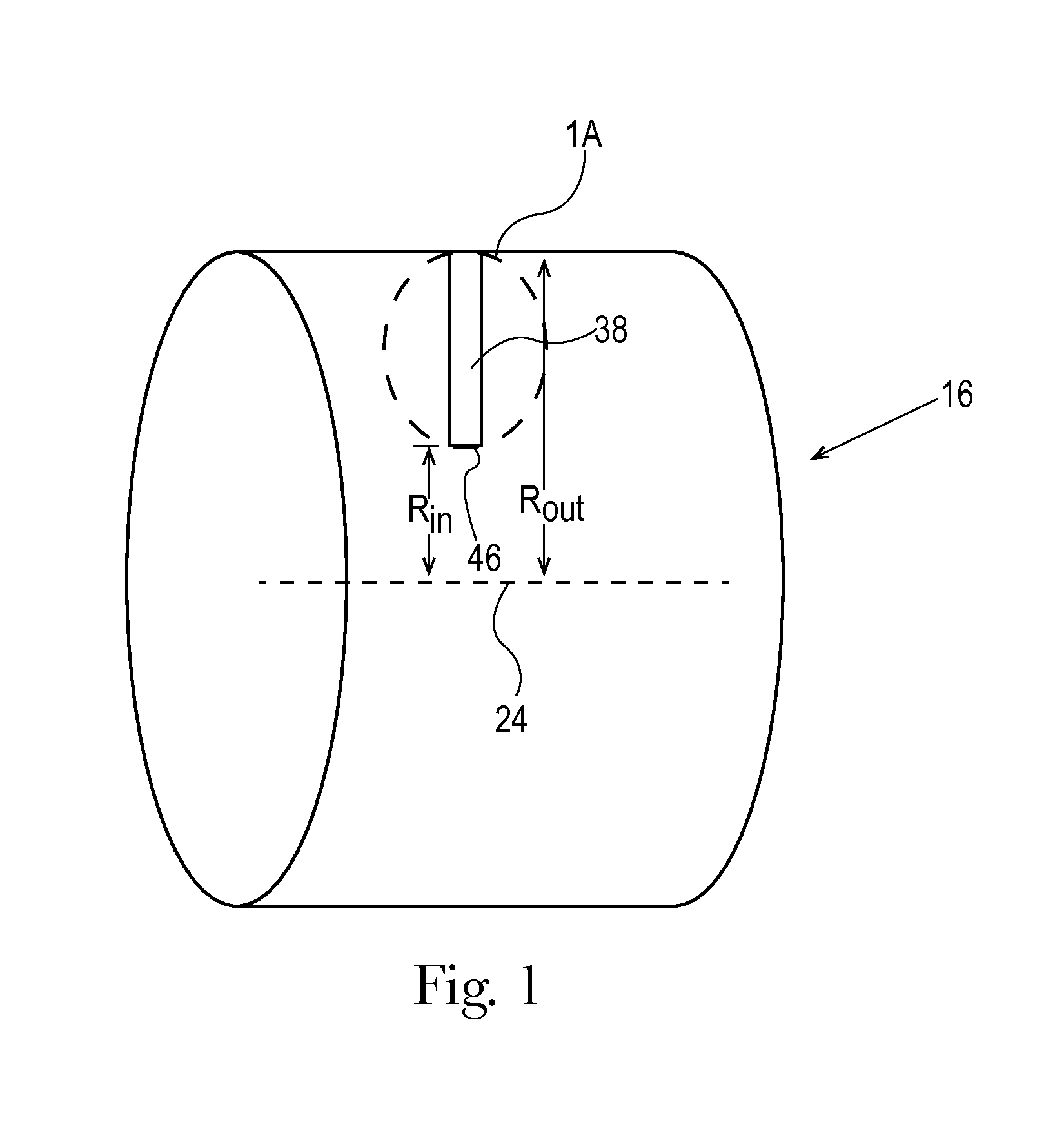
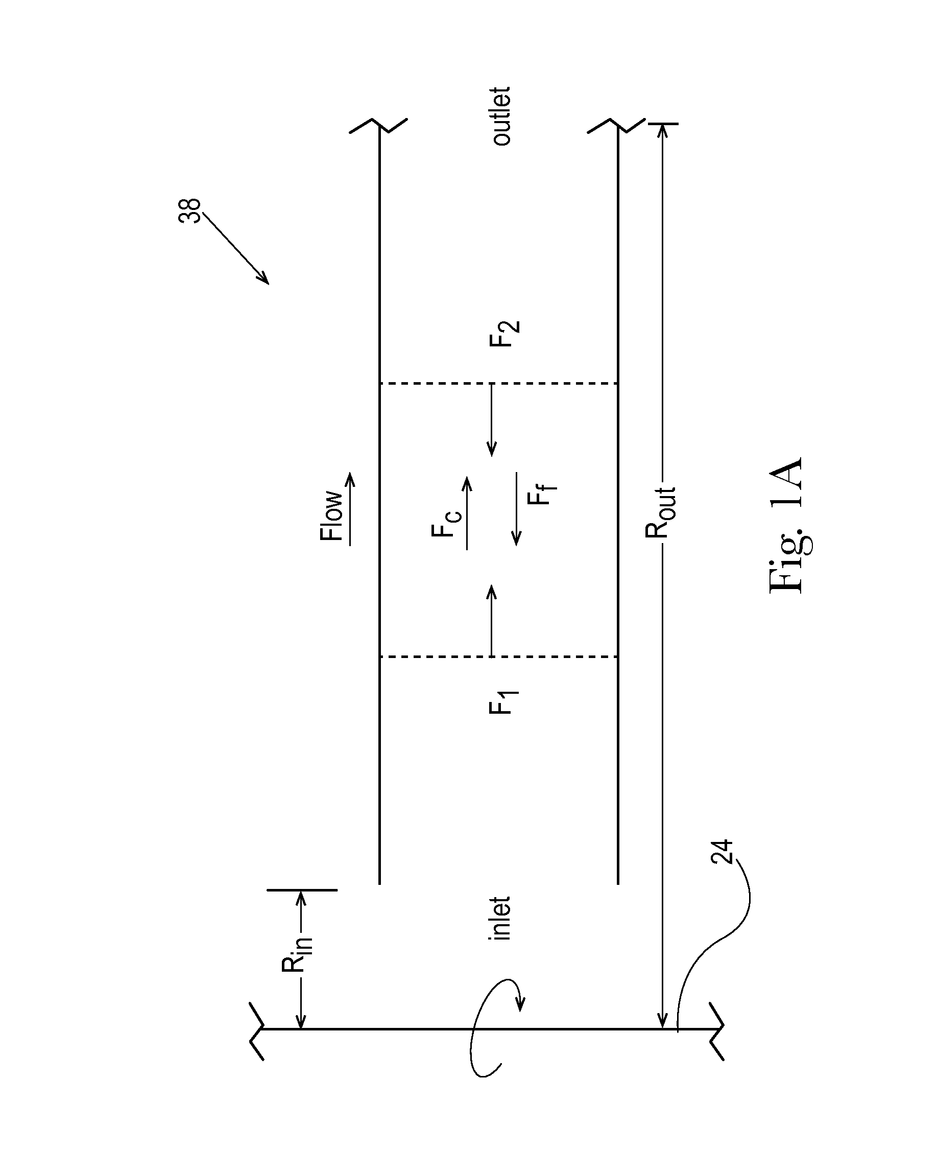
[0032]According to the present description, it is believed that controlling the vaporization (e.g., the formation of gas or air bubbles) in liquids disposed in elongate pipes that can be rotated about an axis can be achieved by advancing the mathematical foundation of the pressures in such systems. In order to understand and evaluate the fluid vaporization process and use the results to describe the unique rotary union described herein, a review of the forces involved in the movement of fluidic media through a pipe (or fluid passage) orbiting about an axis of rotation is necessary. Using these results to design a rotary union suitable for use in high rotational velocity applications can result in the prevention or reduction of fluid vaporization within the fluid passage by careful selection of the position at which a fluid exits a rotary union relative to fluid channels disposed within a rotary device (such as an internally-fed gravure roll) attached and in fluid communication there...


PUM


Abstract

The present disclosure provides for the description of rotary unions. The described rotary unions are provided with a non-rotating union part and a rotating union part affixable to a rotating device. An exemplary rotary union can be positioned relative to a bearing supporting the rotating device and the rotating device or can be incorporated into a bearing supporting the rotating device.

Description

FIELD OF THE INVENTION[0001]The present disclosure relates to rotary unions. More particularly, the present disclosure relates to rotary unions used for supplying and / or removing a pressurized fluid into a high-speed rotating device. The rotary union is provided with a non-rotating union part and a rotating union part affixable to a rotating device. The rotary union can be positioned between a bearing supporting the rotating device and the rotating device. Alternatively, the rotary union can incorporate a bearing supporting the rotating device.BACKGROUND OF THE INVENTION[0002]A rotary union is generally recognized as a mechanism used to transfer fluid (under pressure or vacuum) from a stationary inlet to a rotating outlet. The rotary union is generally capable of preserving and isolating a fluid connection disposed between the stationary inlet and the rotating outlet. Rotary unions are utilized in a variety of applications—from compact rotary unions for the semiconductor industry to...

Claims


Application Information

Patent Timeline
Patent Type & Authority Applications(United States)
IPC IPC(8): F16L27/08
CPCF16L27/082B41F31/22F16L27/087F16L39/06
Inventor CONROY, MARK STEPHENBYRNE, THOMAS TIMOTHYCHEN, HAIBIN
Owner THE PROCTER & GAMBLE COMPANY
Why Eureka
Try Eureka