Apparatus for non-contact cleaning a paint spray tip

a technology of spray tip and cleaning apparatus, which is applied in the direction of cleaning using liquids, burners, combustion types, etc., can solve the problems of uneven spraying of paint, dripping paint, other aesthetic defects, etc., and achieve the effect of fast drying and complete spraying tip

Inactive Publication Date: 2015-04-09
JESSUP PHILIP +1
View PDF8 Cites 14 Cited by
  • Summary
  • Abstract
  • Description
  • Claims
  • Application Information

AI Technical Summary

Benefits of technology

[0013]The housing also includes a heater fluid passageway in close proximity to the solvent passageway as well as the drier air passageway. Preferably, all passageways extend through one or more heat sinks within the housing. Thus, the heat from the heated water flowing through the housing simultaneously heats both the drier air as well as the solvent. This, in turn, facilitates faster and complete drying of the spray tip following a cleaning operation, particularly in the case where the paint is a water-based paint.
[0014]At least one down flow nozzle is positioned beneath the housing opening and is oriented in a direction away from the housing opening. The flow of compressed air through the down flow nozzles effectively creates a lowered pressure region below the housing opening thus drawing air from the drier nozzles downwardly through the housing and across the spray tip.

Problems solved by technology

Otherwise, accumulated paint on the spray tip for the paint sprayers can result in paint drip, uneven paint spray, as well as other aesthetic defects.
When this happens, it is oftentimes necessary to completely remove the paint sprayed on the article and then repaint the article.
This, however, is costly and time consuming.
While adequate drying of the paint spray tip may be achieved by increasing the cycle time for the non-contact cleaning device, such increased cycle time unacceptably increases the cycle time of the overall painting operation.
This, in turn, increases the overall cost of the painting operation.

Method used


Image

  • Apparatus for non-contact cleaning a paint spray tip
  • Apparatus for non-contact cleaning a paint spray tip
  • Apparatus for non-contact cleaning a paint spray tip

Examples


Embodiment Construction

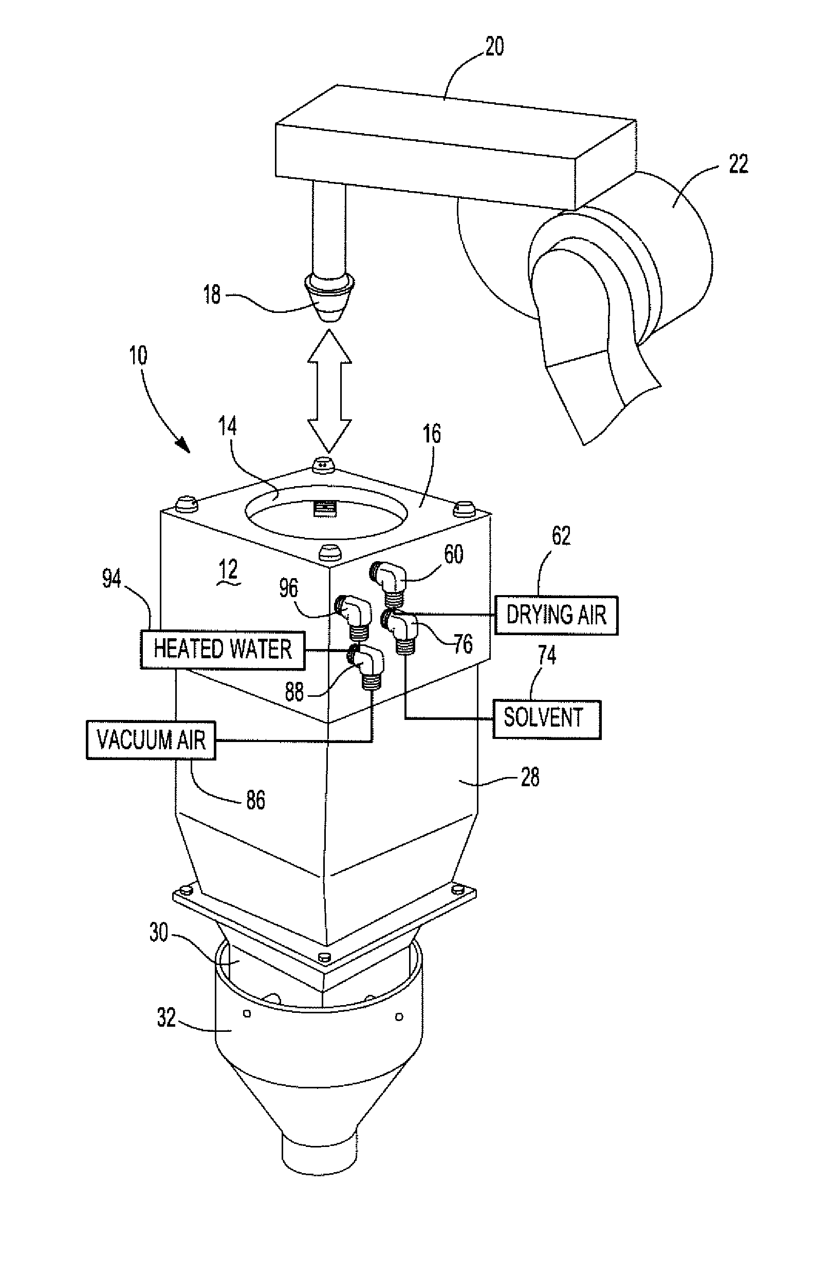
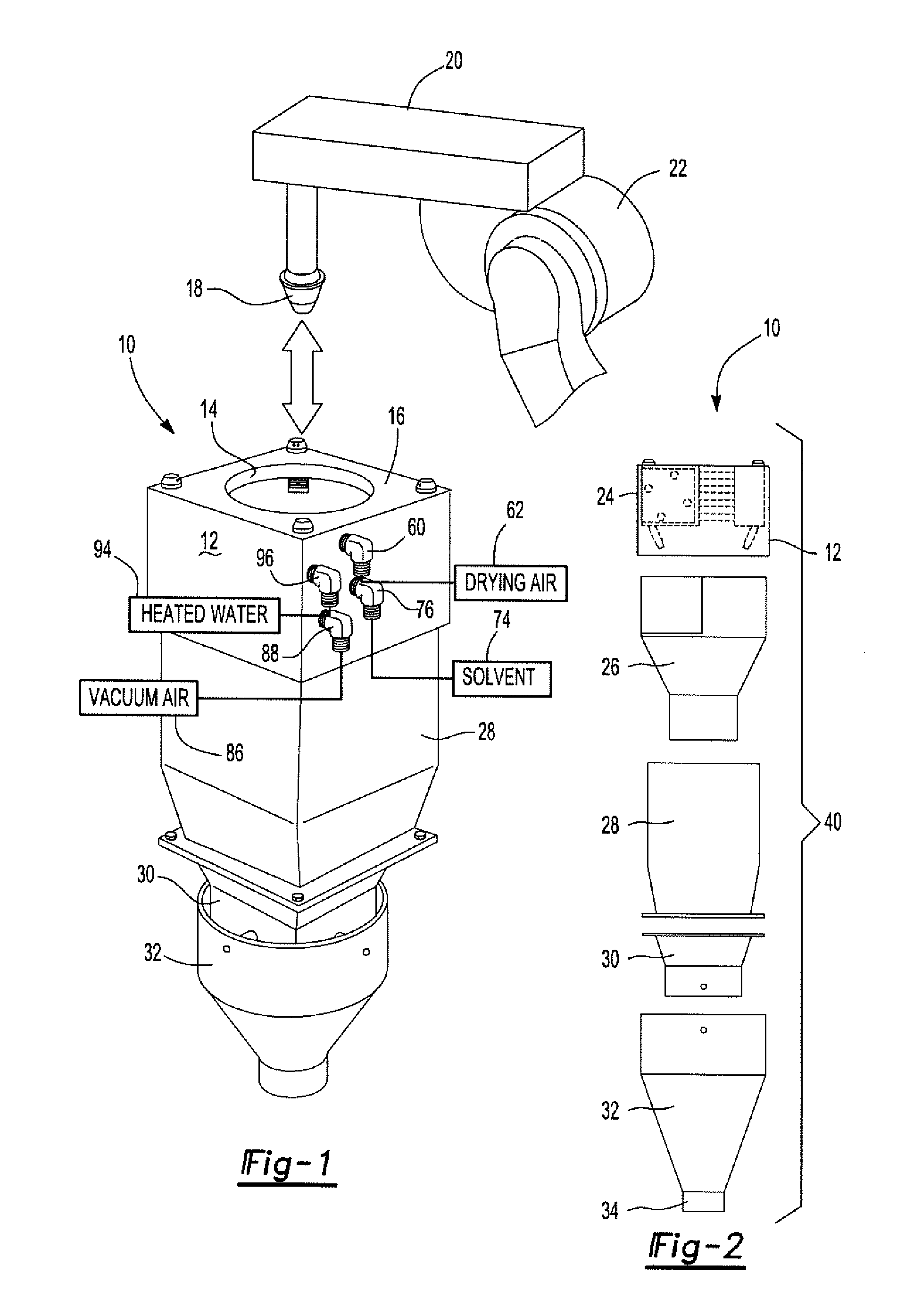
[0023]With reference first to FIGS. 1 and 2, a preferred embodiment of a non-contact cleaning apparatus 10 according to the present invention is shown. The apparatus 10 includes a housing 12 which is constructed from any appropriate material, such as sheet metal. The housing 12 includes a generally circular opening 14 in its top 16. This opening 14, furthermore, is dimensioned to receive a spray tip 18 of a paint spray gun 20, typically manipulated by a robot 22 (only partially illustrated).

[0024]Still referring to FIGS. 1 and 2, the housing 12 preferably includes a plurality of housing sections, including a top section 24 as well as lower housing sections 26, 28, 30, and 32. These housing sections 24-32 are secured together in any appropriate fashion, such as by bolts. In addition, the housing sections 24-32 all include a vertically open passageway so that the solvent may be collected and recycled or disposed of. The air flows through the opening 14 in the top housing section 24, t...


PUM


Abstract

An apparatus for non-contact cleaning a paint spray tip of a spray gun. The apparatus includes a housing with a top and an opening formed in the top to receive the spray tip. At least one drier nozzle is fluidly connected to a source of compressed air so that discharge from the nozzle impinges upon and dries the spray tip. Similarly, at least one solvent nozzle is also attached to the housing around the opening and discharges solvent on the spray tip when positioned in the housing opening. One or more down flow nozzles are also mounted to the housing to create a downdraft through the housing opening to facilitate cleaning and drying of the spray gun spray tip. A heated fluid also flows through the housing in close proximity to the fluid passageways for the drier nozzle and solvent nozzle in order to heat both the drier nozzle air flow and solvent flow to facilitate cleaning of the spray tip.

Description

BACKGROUND OF THE INVENTION[0001]I. Field of the Invention[0002]The present invention relates generally to cleaning devices and, more particularly, to a cleaning device for cleaning the paint spray tip of a spray gun.[0003]II. Description of Related Art[0004]Industrial spray painting equipment is widely used throughout the industry in many different applications. For example, robots manipulate paint spray guns in the automotive industry in order to paint automotive vehicles as well as components for those vehicles.[0005]In many applications it is desirable, indeed oftentimes required, to clean the spray tip of the paint sprayer between spraying operations. Otherwise, accumulated paint on the spray tip for the paint sprayers can result in paint drip, uneven paint spray, as well as other aesthetic defects. When this happens, it is oftentimes necessary to completely remove the paint sprayed on the article and then repaint the article. This, however, is costly and time consuming.[0006]T...

Claims


Application Information

Patent Timeline
Patent Type & Authority Applications(United States)
IPC IPC(8): B05B15/02B05B7/02
CPCB05B7/02B05B15/0258B05B7/1673B08B3/02B05B15/555
Inventor JESSUP, PHILIPJESSUP, ELEANOR
Owner JESSUP PHILIP
Why Eureka
Try Eureka