
Duty correction circuit and method

a duty correction circuit and circuit technology, applied in pulse manipulation, pulse technique, instruments, etc., can solve the problem of data input/output at accurate timings, and achieve the effect of preventing the duty ratio of a clock from being twisted

Inactive Publication Date: 2015-04-09
SK HYNIX INC
View PDF2 Cites 7 Cited by
  • Summary
  • Abstract
  • Description
  • Claims
  • Application Information

AI Technical Summary

Benefits of technology

This patent is directed toward a circuit and a semiconductor device that can prevent the duty ratio of a clock from becoming distorted due to a sudden change in voltage. The technical effect of this invention is to improve the stability and accuracy of computer clocks, which can benefit the performance and reliability of electronic devices.

Problems solved by technology

If the duty ratio of a clock does not accurately become 50%, timing between the rising edge and the falling edge of the clock is twisted, and thus data may not be input / output at accurate timings.

Method used


Image

  • Duty correction circuit and method
  • Duty correction circuit and method
  • Duty correction circuit and method

Examples


Embodiment Construction

[0018]Exemplary embodiments of the present invention will be described below in more detail with reference to the accompanying drawings. The present invention may, however, be embodied in different forms and should not be construed as limited to the embodiments set forth herein. Rather, these embodiments are provided so that this disclosure will be thorough and complete, and will fully convey the scope of the present invention to those skilled in the art. Throughout the disclosure, reference numerals correspond directly to the like numbered parts in the various figures and embodiments of the present invention. It is also noted that in this specification, “connected / coupled” refers to one component not only directly coupling another component but also indirectly coupling another component through an intermediate component. In addition, a singular form may include a plural form as long as it is not specifically mentioned in a sentence.

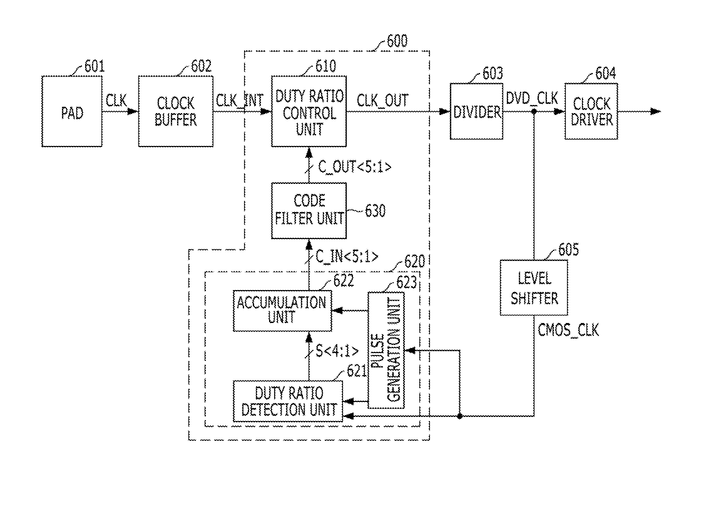
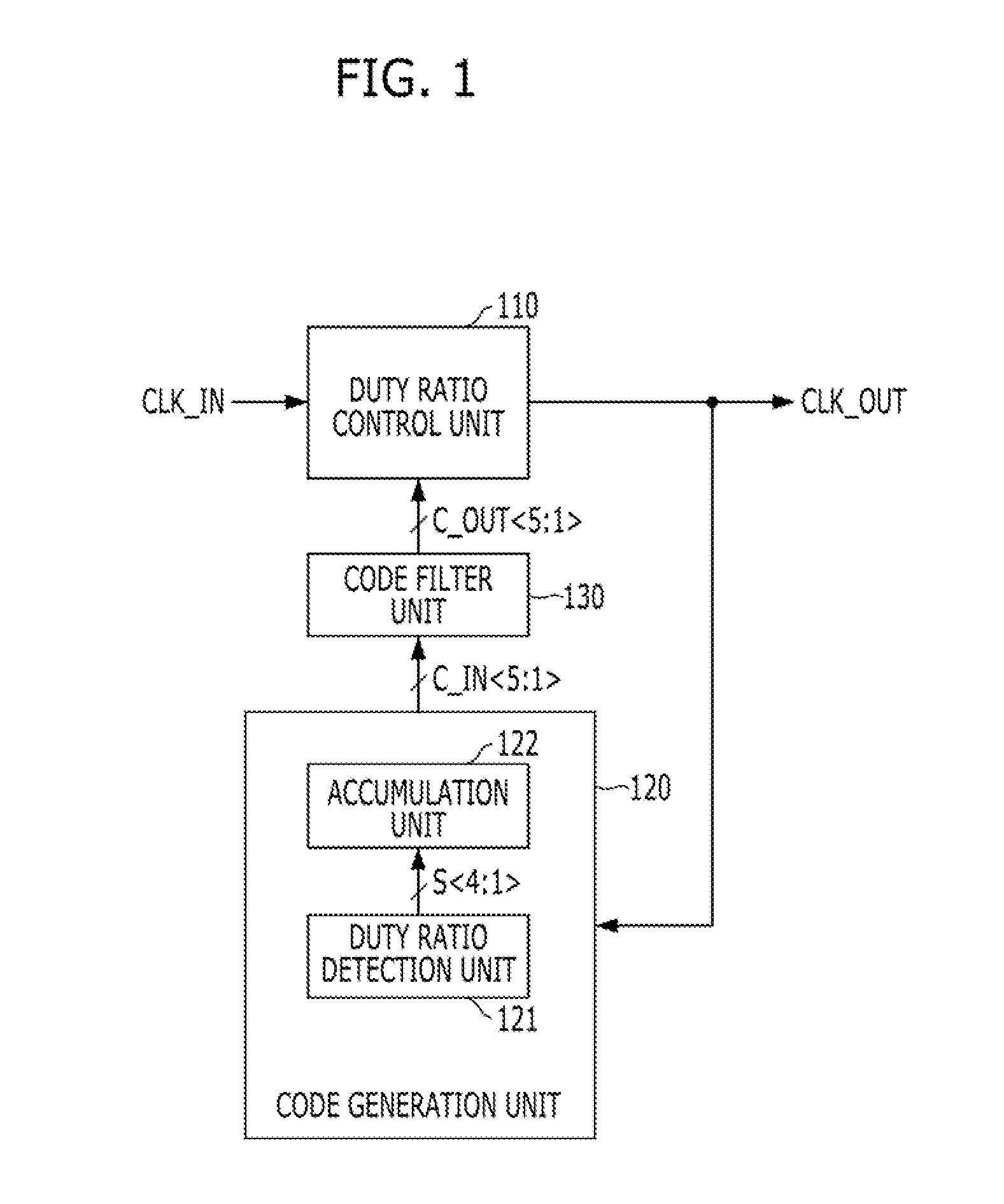
[0019]FIG. 1 is a block diagram illustrating a DCC...


PUM


Abstract

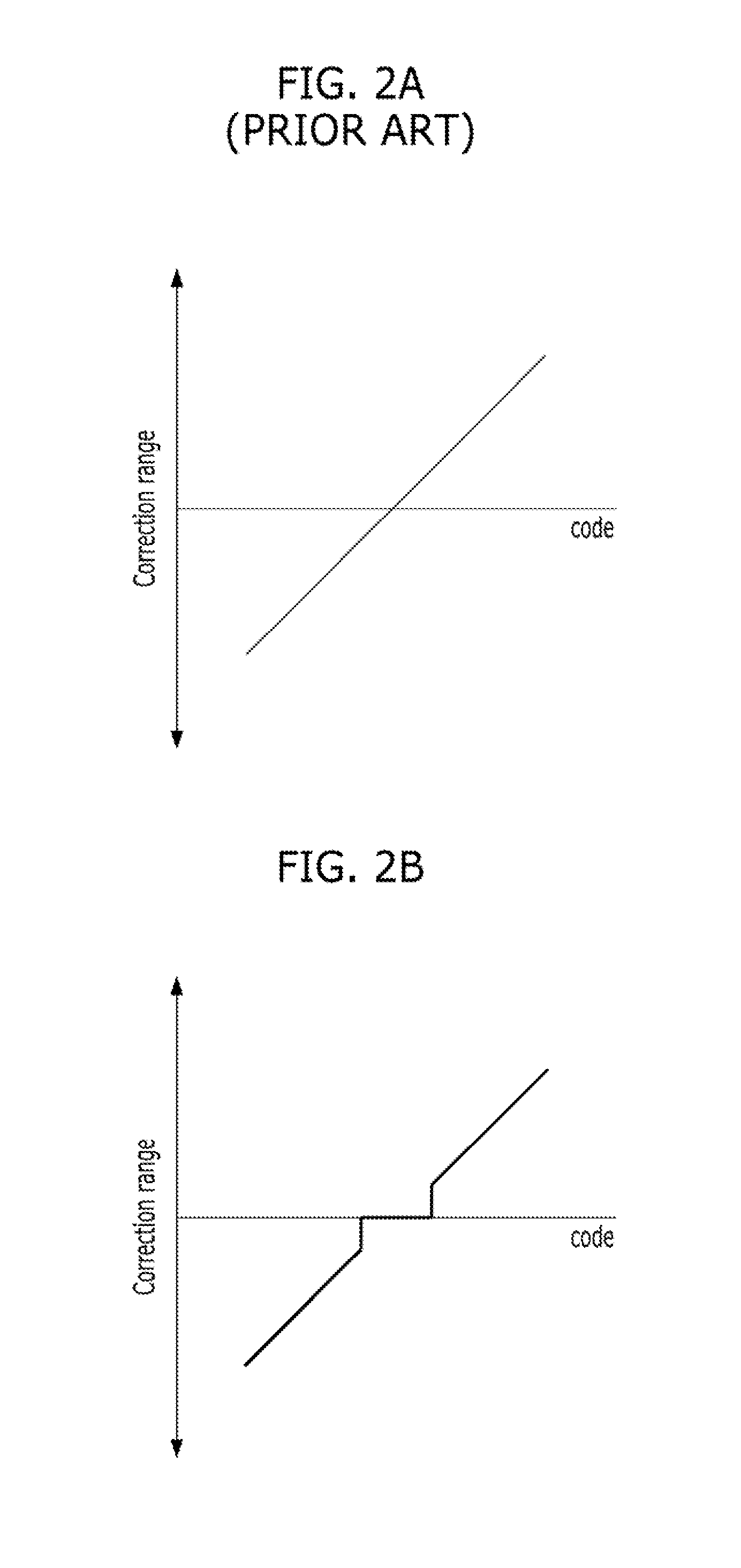
A duty correction circuit includes a duty ratio control unit suitable for generating an output clock by adjusting the duty ratio of an input clock, a code generation unit suitable for detecting a duty of the output clock and generating a first duty ratio control code based on the detection result, and a code filter unit suitable for providing the duty ratio control unit with a second duty ratio control code corresponding to a target value when a value of the first duty ratio control code is within a predetermined critical range adjacent to the target value.

Description

CROSS-REFERENCE TO RELATED APPLICATIONS[0001]The present application claims priority of Korean Patent Application No. 10-2013-0119729, filed on Oct. 8, 2013, which is incorporated herein by reference in its entirety.BACKGROUND[0002]1. Field[0003]Exemplary embodiments of the present invention relate to semiconductor design technology, and more particularly, to a duty correction circuit (DCC).[0004]2. Description of the Related Art[0005]In semiconductor devices operating based on a clock, such as synchronous memory devices, to accurately control the duty ratio of a clock is very important. For example, if the duty ratio of a clock is 50%, it means that a high pulse section and a low pulse section of the clock have the same width.[0006]In the synchronous memory devices, data needs to be input / output in accurate synchronism with the rising edge and the falling edge of a clock. If the duty ratio of a clock does not accurately become 50%, timing between the rising edge and the falling edg...

Claims


Application Information

Patent Timeline
IPC IPC(8): H03K3/017
CPCH03K3/017H03K5/1565G11C8/00G11C7/22
Inventor SHIN, DONG-SUKLEE, HYUN-WOO
Owner SK HYNIX INC
Learn More