Clipping tool

Inactive Publication Date: 2015-04-16
ROLLS ROYCE PLC
View PDF1 Cites 0 Cited by
  • Summary
  • Abstract
  • Description
  • Claims
  • Application Information

AI Technical Summary

Benefits of technology

The patent describes a device called a stripper element that helps to automate the removal of flash from a punch. This makes the clipping operation faster and more efficient. Additionally, the device prevents the flash from falling on the riser, which can cause damage to the tooling. Overall, this technology improves the production process.

Problems solved by technology

A problem with conventional clipping tools is that the clipped flash tends to be retained on an outer surface of the punch due to hoop stresses within the sheared material.
Repeated clipping operations can lead to a build-up of clipped flash on the punch which can interfere with the proper operation of the tool.
However, if the flash is simply pushed off the punch after each clipping operation, it can accumulate in the vicinity of the riser, causing mis-loads and damage to tooling.

Method used


Image

  • Clipping tool
  • Clipping tool
  • Clipping tool

Examples


Embodiment Construction

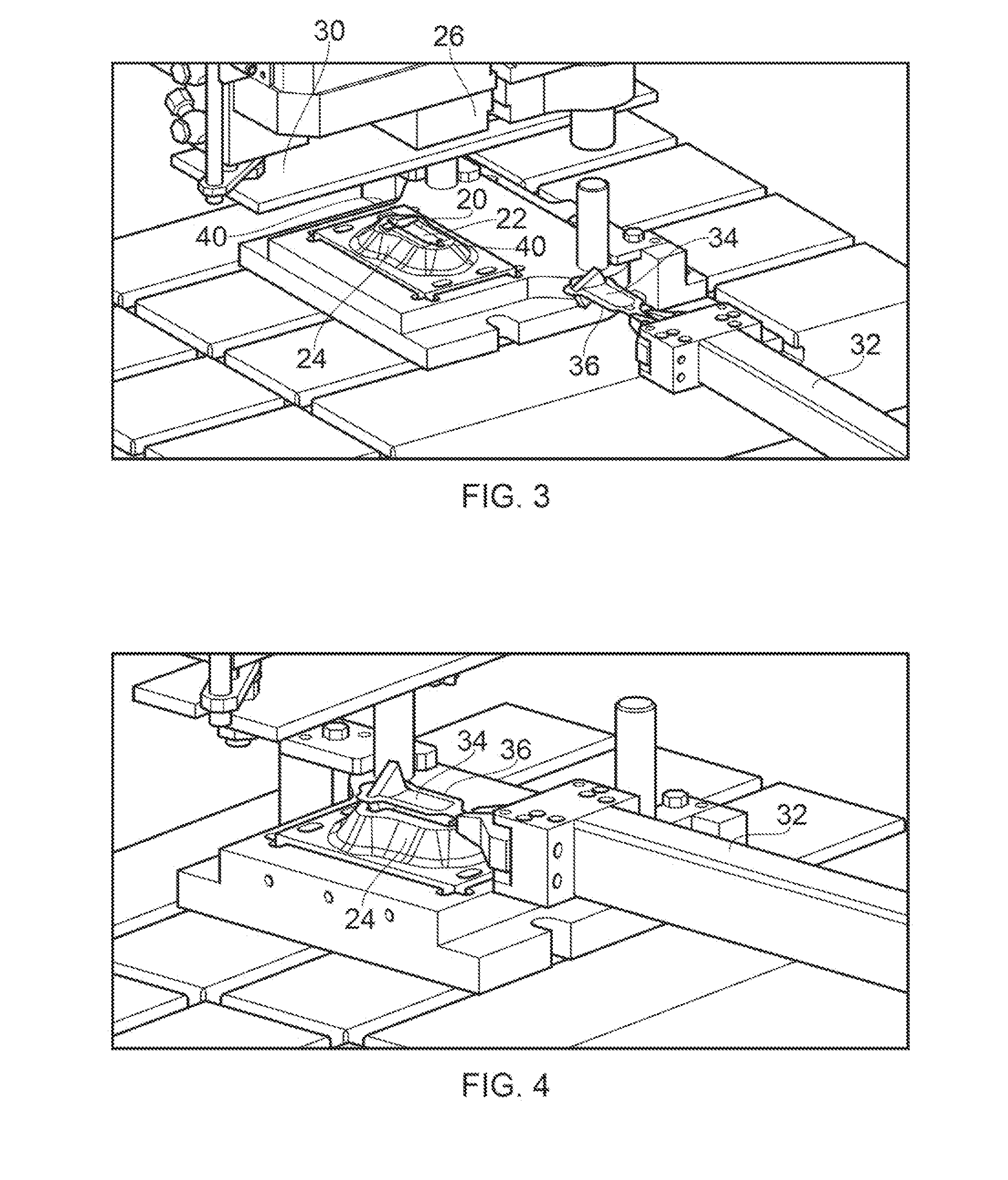
[0030]FIGS. 3 to 18 show a clipping operation using a clipping tool of the present invention.

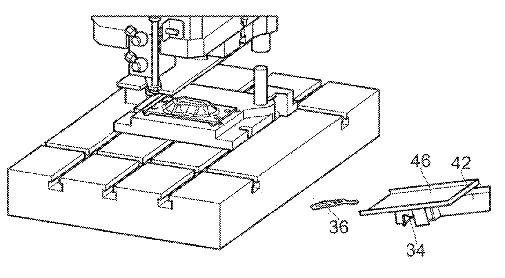
[0031]As shown in the perspective view of FIG. 3, the tool includes a hydraulically cushioned riser 20 having a support surface 22 for an aerofoil blade. A tool body 24 surrounds the riser and provides a clipping aperture through which the riser can descend. An upper ram 26 carries a punch 28 (shown in FIG. 6) and a hydraulically operated stripper plate 30 containing a further aperture through which the punch extends.

[0032]A first robot arm 32 carries a forged aerofoil blade 34 to the riser 20, the blade having a border of surrounding flash 36. The robot arm deposits the blade onto the support surface 22 of the riser 20 (FIG. 4 perspective view), and then withdraws, leaving the blade in position to be clipped (FIG. 5 perspective view). The blade has reference portions 38 at each end which are received in corresponding reference members 40 of the riser to properly locate the blade on the rise...


PUM

PropertyMeasurementUnit
Gravityaaaaaaaaaa

Abstract

A clipping tool for clipping flash from a forged component is provided. The clipping tool includes: a riser having a support surface for supporting the component; a punch for gripping the component on the support surface such that the flash projects laterally from the riser and the punch; and a tool body having an aperture through which the riser and the punch are translatable to shear the projecting flash from the gripped component, the sheared flash being pushed by the tool body over an outer surface of the punch. The clipping tool further includes: a controllably movable receptacle which, when the punch is withdrawn from the aperture, is interposed between the punch and the riser; and a stripper element which is actuatable to strip the sheared flash from the outer surface of the punch, the stripped flash being received by the interposed receptacle, which is then moved to dispose of the stripped flash.

Description

FIELD OF THE INVENTION[0001]The present invention relates to a clipping tool for clipping a component and particularly but not exclusively to a clipping tool for clipping a forged component such as a gas turbine aerofoil body.BACKGROUND OF THE INVENTION[0002]Metal components are forged by applying compressive loads to form the metal into the desired shape. This is conventionally achieved by placing the metal between two dies which are forced together such that the metal forms into the interior profile of the dies. In doing so, metal is often forced through the interface of the two dies, the parting line, creating a burr around the component, known as flash. The flash can be removed by a subsequent clipping or trimming process.[0003]Conventionally, clipping processes use a clipping die to hold a component as it is forced through clipping steels having an aperture sized to the desired final shape of the component. The component is placed on top of the die so that the flash extends out...

Claims


Application Information

Patent Timeline
IPC IPC(8): B26D7/18B21J1/00
CPCB26D7/18B21J1/00B26D2007/0018B26D2007/1809B21J5/027Y10T83/2098
Inventor MCBAIN, JOHN
Owner ROLLS ROYCE PLC
Why Eureka
Try Eureka