Electronic apparatus and protecting method thereof
a technology of electronic equipment and protection method, applied in the direction of electric controller, dynamo-electric converter control, electric controller details, etc., can solve the problems of increasing the size of the apparatus, damage to the precision device, and collision between the precision device and the surrounding structure of the electronic apparatus
- Summary
- Abstract
- Description
- Claims
- Application Information
AI Technical Summary
Benefits of technology
Problems solved by technology
Method used
Image

Examples
first embodiment
The First Embodiment
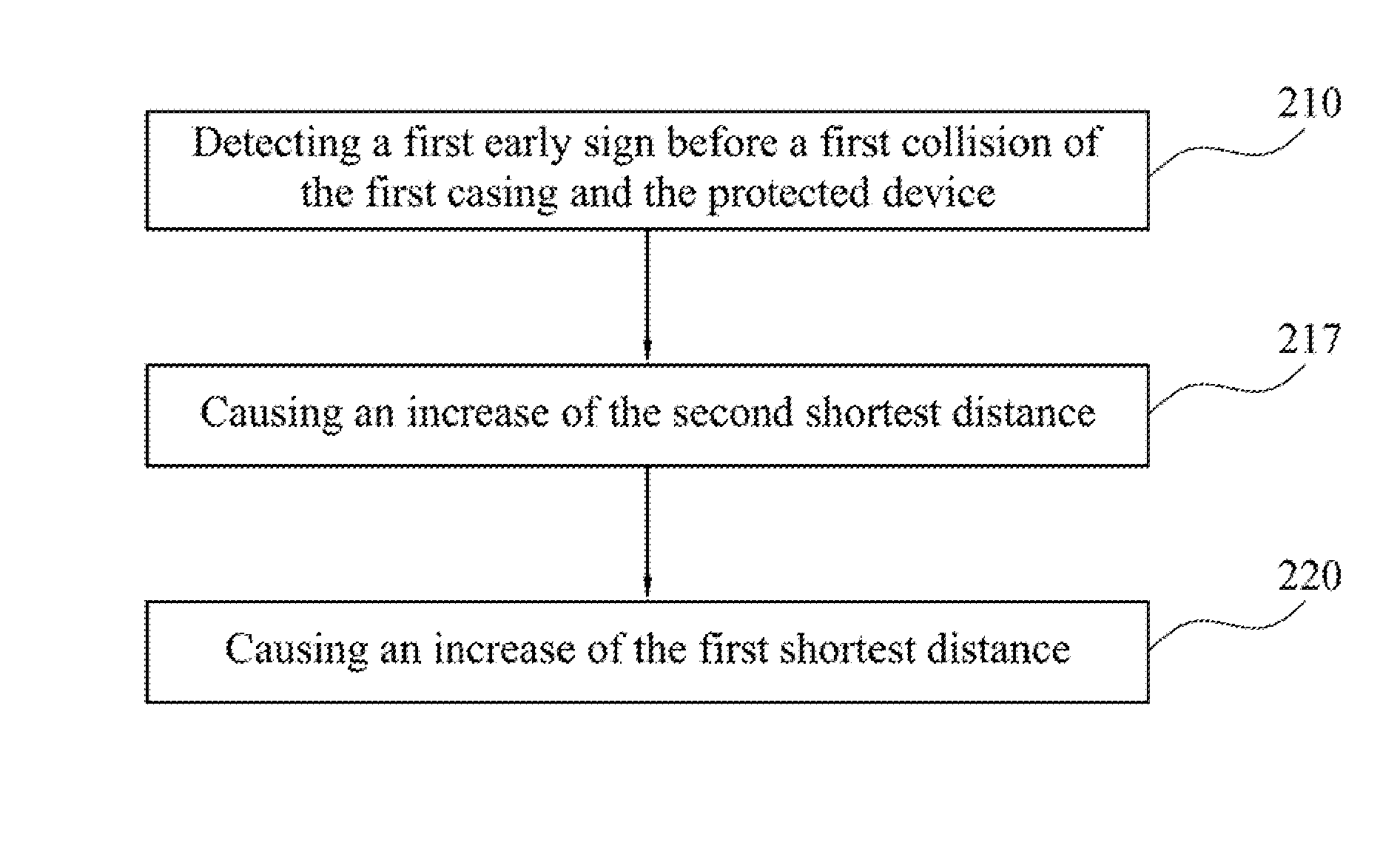
[0060]FIG. 4 is a three-dimensional drawing of the electronic apparatus 100 according to the first embodiment of the present disclosure, in which the second casing 115 is removed. FIG. 5 is a function block diagram of the electronic apparatus 100 of FIG. 4. As shown in FIGS. 4-5, an electronic apparatus 100 includes a first casing 110, a protected device 120, a detector 130, an actuator 140 and a controller 150. The protected device 120 is spaced apart from the first casing 110 by a first shortest distance D1 (as shown in FIGS. 6-8). The detector 130 is configured to detect a first early sign before a first collision of the first casing 110 and the protected device 120. The controller 150 is configured to actuate the actuator 140 after the detector 130 has detected the first early sign, causing an increase of the first shortest distance D1 (as shown in FIGS. 6-8), and subsequently the first collision of the first casing 110 and the protected device 120 is avoided...
second embodiment
The Second Embodiment
[0074]FIG. 9 is a function block diagram of the electronic apparatus 100 according to the second embodiment of the present disclosure. The difference between this embodiment and the first embodiment is that: this embodiment directly applies the piezoelectric piece as the detector 130, while omitting the set up of the accelerometer.
[0075]Generally speaking, there are two types of piezoelectric effect of the piezoelectric piece. One is the direct piezoelectric effect; another is the converse piezoelectric effect. When the piezoelectric piece is subjected to an electric field, an electric dipole moment will be stretched or shortened, such that the piezoelectric piece deforms. This converts an electrical energy to a mechanical energy. This is known as the direct piezoelectric effect. In contrast, when the piezoelectric piece deforms, the electric dipole moment in the piezoelectric piece will also change with the deformation. In order to resist against this tendency,...
third embodiment
The Third Embodiment
[0083]FIGS. 10-11 are schematic sectional views of the electronic apparatus 100, according to the third embodiment of the present disclosure, upon an impact at the second casing 115. The difference between this embodiment and the first embodiment is that: this embodiment has also the actuator 140 on the second casing 115. Moreover, the detector 130 is further configured to detect a second early sign of the second collision of the second casing 115 and the protected device 120. The controller 150 is further configured to actuate the actuator 140 on the second casing 115 after the detector 130 has detected the second early sign, causing an increase of the second shortest distance D2.
[0084]To be more specific, when the detector 130 is the accelerometer, as the acceleration detected has a direction, the upcoming impact on the first casing 110 or the second casing 115 can be predicted (i.e., the first early sign or the second early sign can be determined) according to...
PUM
 Abstract
Description
Claims
Application Information
 - R&D Engineer
- R&D Manager
- IP Professional
- Industry Leading Data Capabilities
- Powerful AI technology
- Patent DNA Extraction
Browse by: Latest US Patents, China's latest patents, Technical Efficacy Thesaurus, Application Domain, Technology Topic.
© 2024 PatSnap. All rights reserved.Legal|Privacy policy|Modern Slavery Act Transparency Statement|Sitemap