Indicator lamp having a converging lens

a technology of converging lens and indicator lamp, which is applied in the field of indicator lamp, can solve the problems of deteriorating long distance visual recognition property, lack of directivity of pin-point light emission, scattered light emission, etc., and achieves smooth and efficient

Inactive Publication Date: 2009-01-06
OKAYA ELECTRIC INDS
View PDF20 Cites 113 Cited by
  • Summary
  • Abstract
  • Description
  • Claims
  • Application Information

AI Technical Summary

Problems solved by technology

Such pin-point light emission lacks directivity and is scattered.
It is thus impossible to form a substantially fixed planar light-emission area.
Besides, the long distance visual recognition property is deteriorated.
However, since the scattering of light is suppressed, a problem is posed in that the visual field angle as visual range is reduced.
The forming of a lens having such a complicated structure encounters great difficulty.
Particularly, in the case of a lens body having a certain height, the ring-like groove may become too deep, and depending on the size and material of the lens, light emitted from the light-emitting element may not always smoothly and efficiently proceed as emission light flux forwards.

Method used


Image

  • Indicator lamp having a converging lens
  • Indicator lamp having a converging lens
  • Indicator lamp having a converging lens

Examples


first embodiment

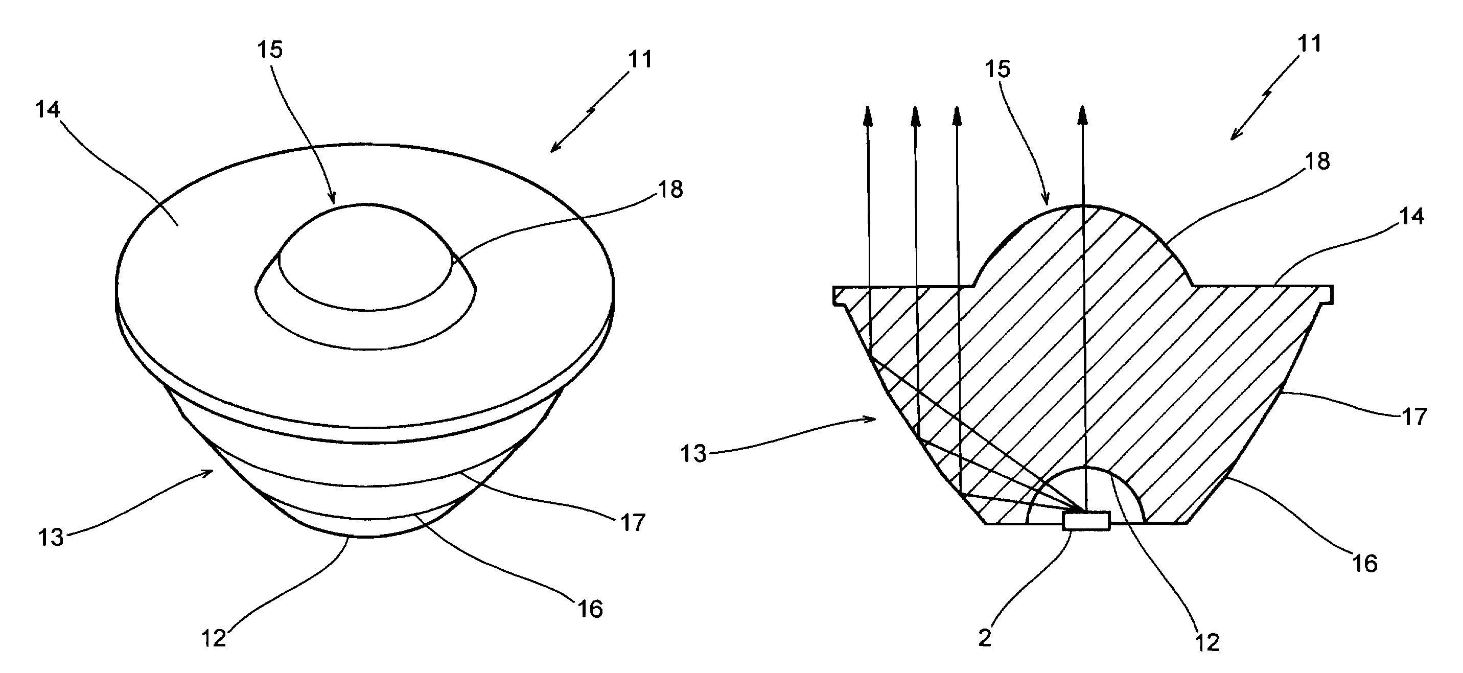
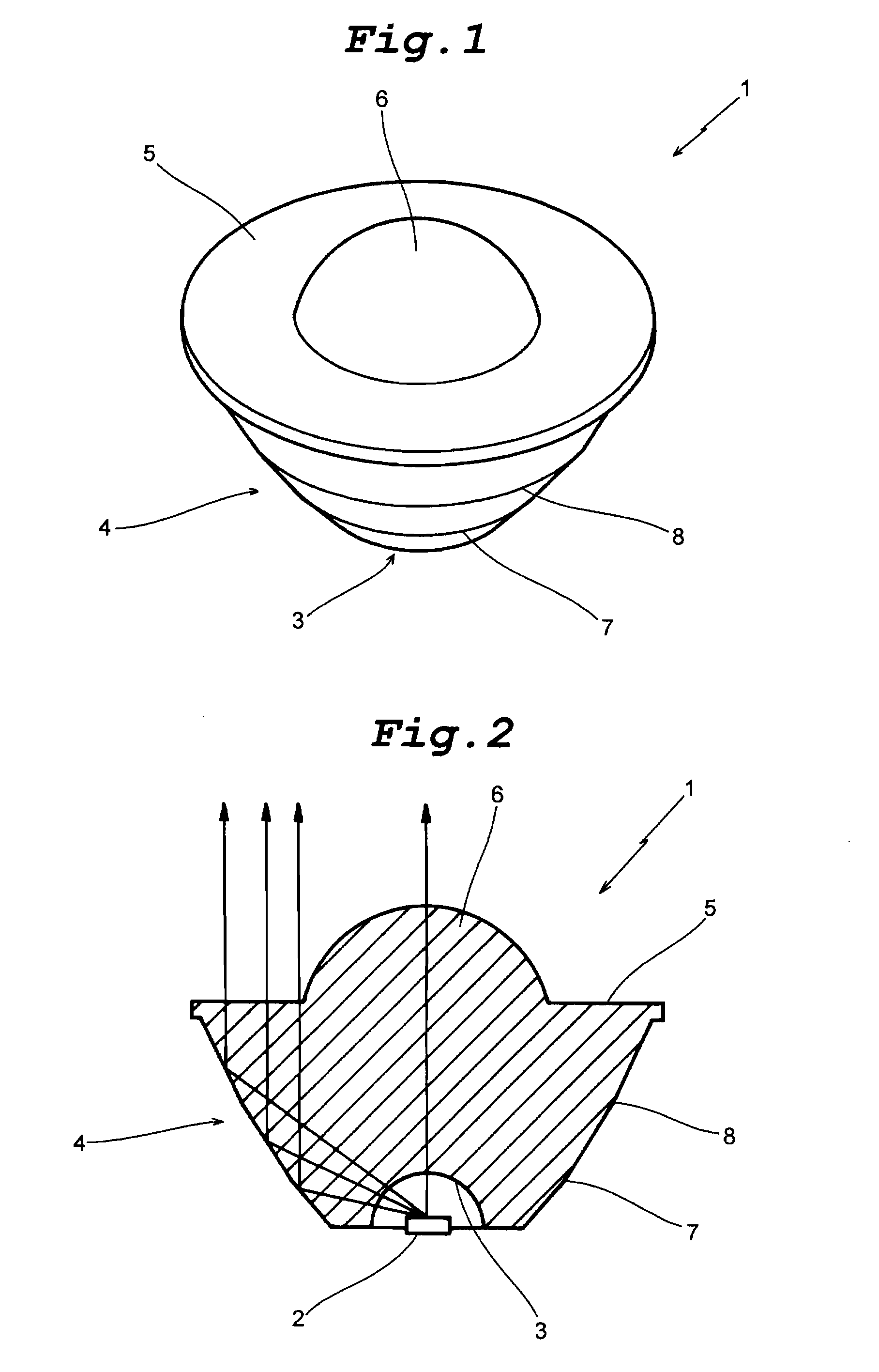
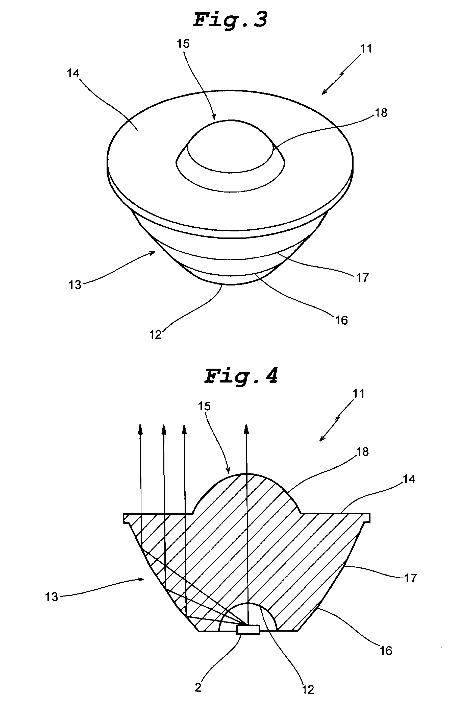
[0029]FIGS. 1 and 2 show the indicator lamp according to the invention. A light-emitting element lens 1 which is obtained by processing a transparent polymer material into a substantially conical shape, has a light-emitting element mounting cavity 3 formed in its bottom for disposing a light-emitting element 2 such as a LED in the cavity. The lens 1 has a sloped peripheral surface 4. The angle of the peripheral surface 4 with respect to the lens axis becomes progressively smaller in three stages from the bottom toward the front of the lens. The lens front surface 5 is flat and has a central forwardly convex lens part 6 (R5.78). The lens front surface 5 is made broader by forming a slightly projecting flange-like edge. As for the three-stage sloped parts of the peripheral surface 4, their angles with respect to the lens axis are set up to 40.61 degrees, 32.19 degrees and 26.87 degrees, respectively, (or may be other angles, of course) from the bottom toward the lens front. The circum...

fourth embodiment

[0033]FIGS. 7 and 8 show the indicator lamp according to the invention. In this embodiment, the light-emitting element lens 31, which is made of a transparent polymer material such as acrylic resin and has a maximum outer diameter of about 21 mm and a height of about 12.5 mm, has an inverted conical shape with the outer diameter thereof increasing as one goes upwards. The light-emitting element 2 is disposed at the bottom of the lens, and its emitted light is converged and proceeds as a certain degree of emission light flux forwardly of the lens. This light-emitting element lens 31 has a peculiarly curved peripheral surface slightly outwardly swelling from the bottom towards the front surface 34 of the lens (a plurality of slipped surface parts being possible instead of the curved peripheral surface). The lens front surface 34 has an outer flat surface part 35 and a central forwardly convex lens part 36 (R5) forwardly projecting from a position slightly on the rear side of the lens ...

fifth embodiment

[0040]While the above embodiment is concerned with the structure that the central convex lens part 70 is provided on the front surface of the full reflection lens 64, this is by no means limitative; for instance, the lens front surface may be made fully flat and free from any central convex lens part. Even in this case, although not a perfect parallel light flux as in the case of the indicator lamp 61 described above, this embodiment of the indicator lamp can provide a converging function to provide a roughly parallel light flux of a simple shape. Although not illustrated, with such an arrangement that light is not caused by the front surface 68a of the cavity 68 to proceed straight but diffracted for deviation toward the lens axis, it is possible to provide a more suitable converging function to provide light close to a parallel light flux.

POSSIBILITY OF INDUSTRIAL UTILIZATION

[0041]In the indicator lamp according to the invention, the light-emitting element lens is constituted by a...


PUM


Abstract

It is sought to provide an indicator lamp, which is excellent not only in short distance visual recognition property but also in long distance one, as well as being further excellent in sight field angle property.An indicator lamp includes a light-emitting element 1 and a light-emitting element lens 2 having a light-emitting element mounting cavity 3 formed at the bottom, in which the light-emitting element disposed in the cavity 3 emits light to be fully reflected by the peripheral surface of the lens 1 and proceeds as emission light flux forwardly of the lens 1. The slope angle of the peripheral surface with respect to the lens axis is reduced progressively from the bottom toward the lens front surface 5 in three stages, thus forming circumferential corners 7 and 8 as boundaries between adjacent ones of the three stages. The circumferential corners scatter light emitted from the light emitting element 2 to provide concentric emission light fluxes as viewed from the side of the lens front.

Description

BACKGROUND OF THE INVENTION[0001]1. Field of the Invention[0002]This invention relates to an indicator lamp comprising a light-emitting element such as a LED (light-emitting diode) and a chip and a converging lens disposed atop and covering the light-emitting element to converge light emitted from the element and, more particularly, to an indicator lamp, which permits a small-size light-emitting element to emit light appropriately in a broad light-emission area and with good efficiency.[0003]2. Prior Art[0004]The light emission zone of a light-emitting element such as a LED is intrinsically a pin-point. Such pin-point light emission lacks directivity and is scattered. It is thus impossible to form a substantially fixed planar light-emission area. Besides, the long distance visual recognition property is deteriorated. Accordingly, a converging lens is usually disposed, which covers the front of the light-emitting element and converges the emitted light.[0005]An indicator lamp using s...

Claims


Application Information

Patent Timeline
Patent Type & Authority Patents(United States)
IPC IPC(8): F21V5/04F21K99/00F21S8/00H01L33/58H01L33/60
CPCF21K9/00F21V5/04F21V7/0091F21W2111/00H01L33/58H01L33/60Y10S362/80F21K9/69
Inventor SHIMADA, TOSHIO
Owner OKAYA ELECTRIC INDS
Why Eureka
Try Eureka