
System and method for multi-stage data logging

a data logging and multi-stage technology, applied in the field of data logging, can solve the problems of increasing the number of input ports, the complexity of the processing system, and the disadvantage of the prior art logger architecture, and achieve the effect of increasing the input capacity and high distribution flexibility

Inactive Publication Date: 2005-03-22
NICE SYSTEMS +1
View PDF24 Cites 68 Cited by
  • Summary
  • Abstract
  • Description
  • Claims
  • Application Information

AI Technical Summary

Benefits of technology

Accordingly, it is an object of the present invention to provide a multi-stage data logging system that overcomes problems associated with prior art solutions, and helps meet the market demands for increased input capacity, high distribution flexibility and fault tolerance.
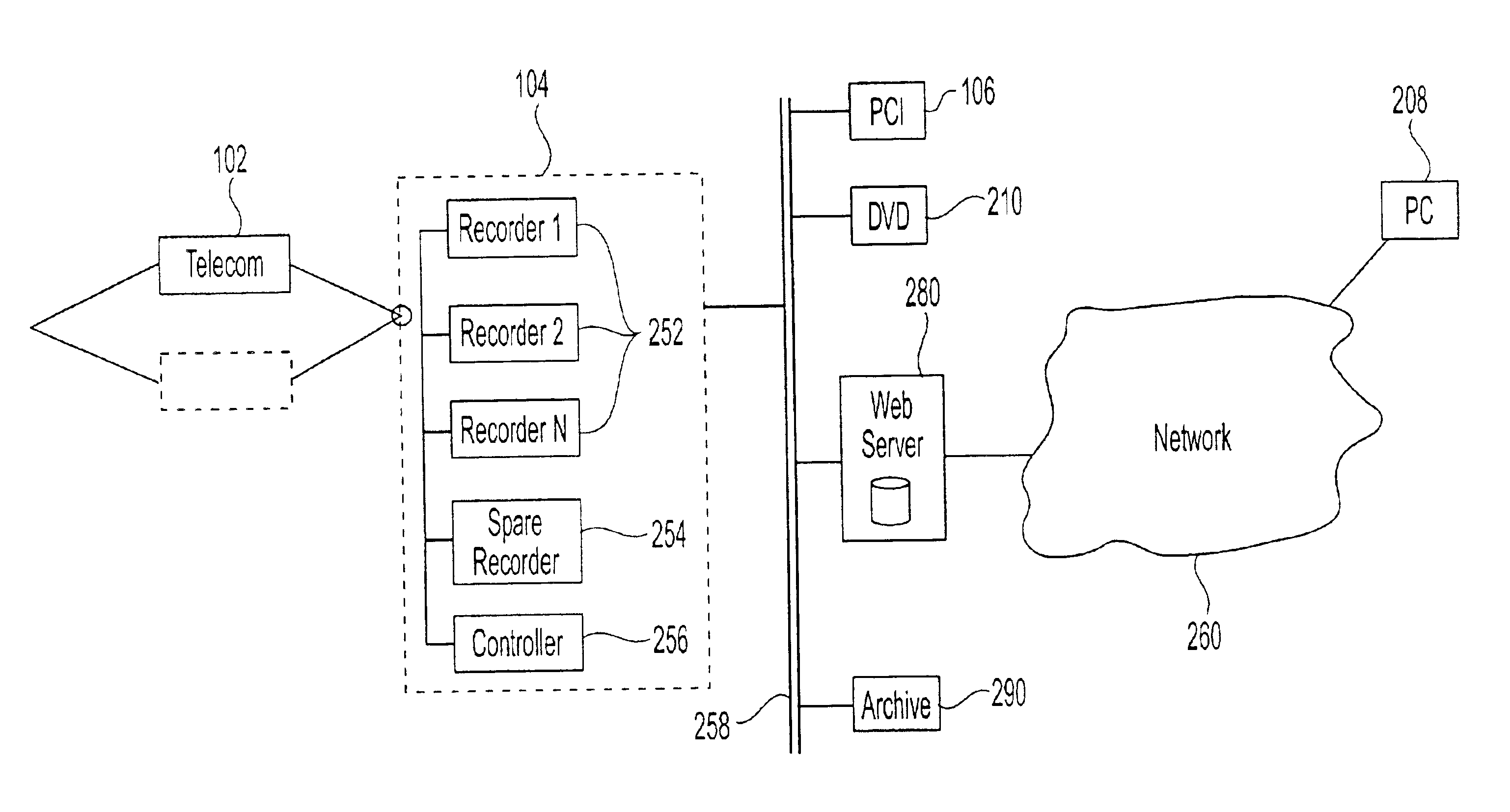
In another preferred embodiment, the recorder stage of the data logging system comprises at least one backup recorder, and the system has means for detecting malfunctions in recorders of the recorder stage, and for automatically switching interface links from the detected malfunctioning recorder to the backup recorders. Related to this embodiment is another aspect of this invention, which is a method for operating a multi-stage data logging system comprising: detecting a malfunctioning recorder in the recorder stage; automatically switching interface links from the detected malfunctioning recorder to a backup recorder to ensure uninterrupted operation of the system; and without disrupting the operation of the system replacing the detected malfunctioning recorder with a functioning recorder.
In yet another aspect, the invention is a method for increasing the capacity of a multi-stage logger system comprising: without disrupting the operation of the system attaching to a network-based or four-wire-based interface between the telecom and the recorder stages at least one recorder so that the combined capacity of the recorders in the recorder stage is equal to or exceeds a given number of channels; and / or attaching at least one additional telecom block to increase the input channel capacity of the system.

Problems solved by technology

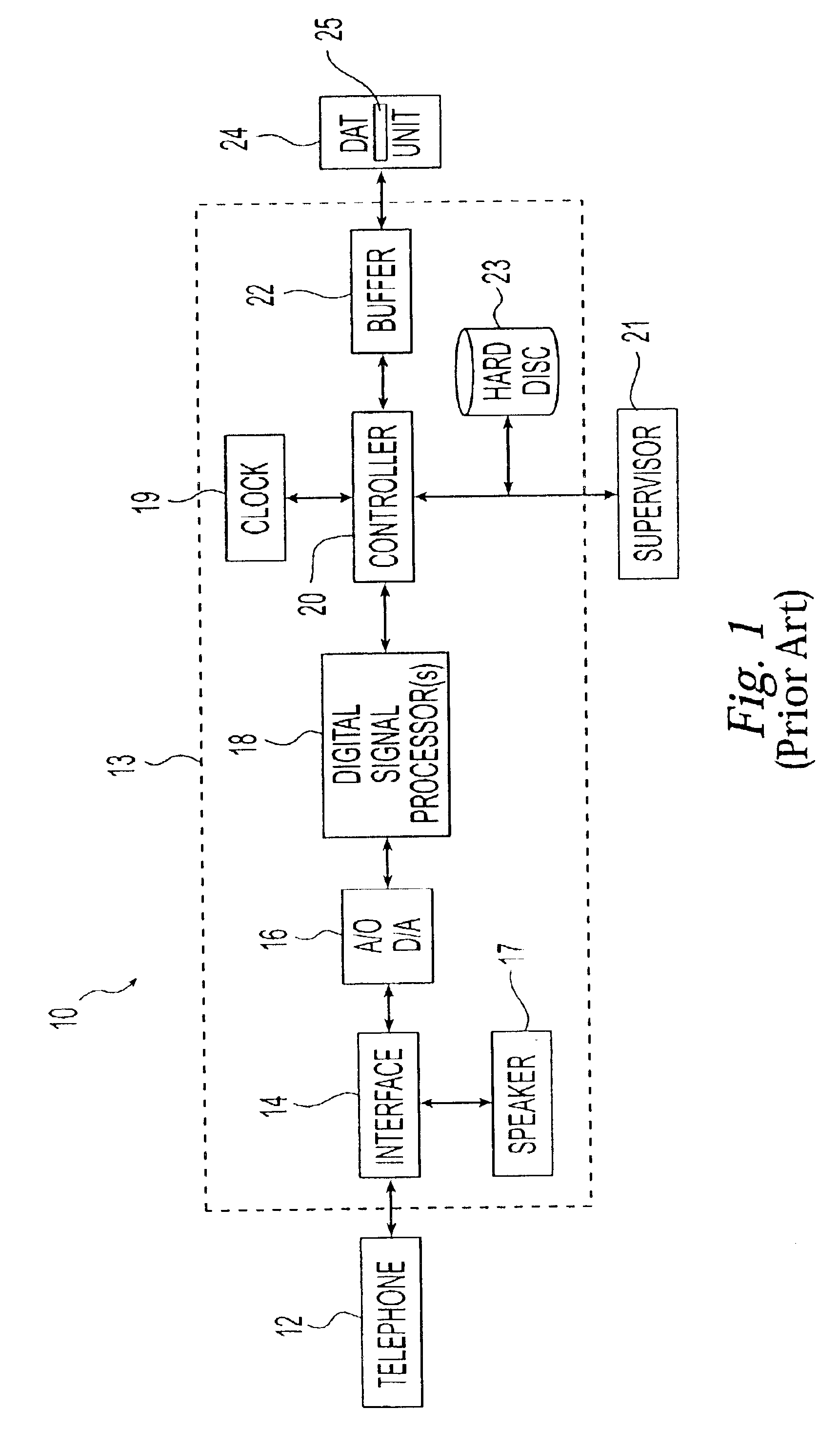
Two strong market demands render prior art logger architectures at a disadvantage in this regard: the need to increase the number of input ports, and the need to provide simple and efficient access to the recorded information in platform-and media-independent ways.
It should be apparent that as the number of channels increases so does the complexity of the processing system.
The increased complexity in turn creates at least two potential problems: (a) diminished fault tolerance of the system; and (b) practical constraints on the physical design, including the weight and size of the system, its wiring and power requirements, among others.
Increasing the system's complexity generally results in a greater vulnerability and higher risk of data losses because of the increased probability that one or more system components can malfunction.
However, people of skill in the art would recognize that in many applications it is critically important that the operation of the system remain error-free.
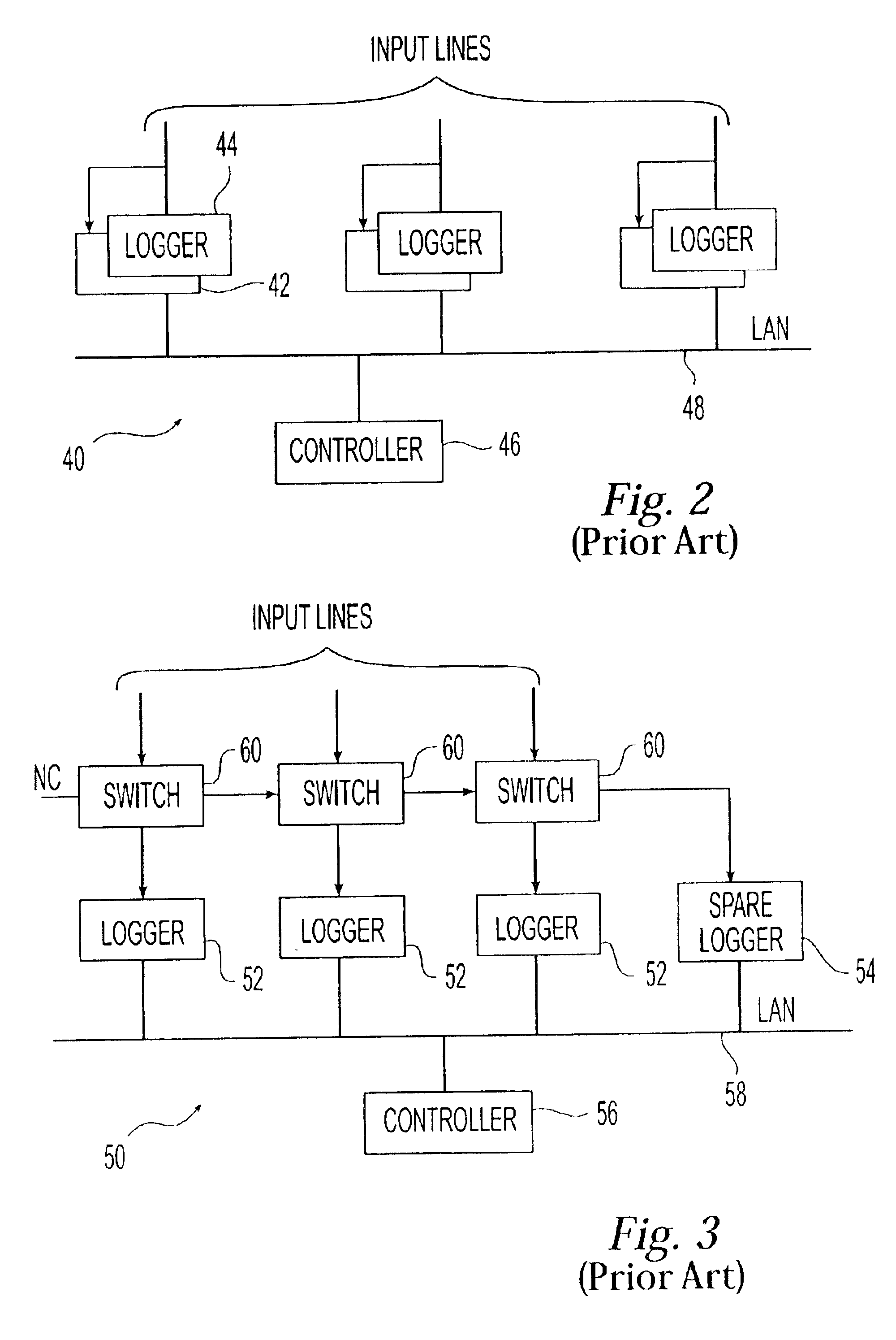
This fault tolerant architecture is wasteful and impractical, because it requires more space and twice the hardware (at twice the cost) of a comparable standard logger system.
Accordingly, it does not take advantage of the fact that in operation certain components of the logger fail much more frequently than others.
As mentioned above, the increased complexity of the system also poses wiring, size and other practical problems.
However, this location may not always be optimal, desirable or even possible in practice.
In particular, spatial constraints as well as security issues pose serious problems.
Thus, the large size of a high-capacity logger can make it impossible to install it in certain locations.
It may further be costly and / or impractical to run massive cable bundles from the PBX room to the loggers.
For security reasons it may not even be desirable that the logger is anywhere near the PBX.
It should thus be apparent that prior art systems implemented as single physical units suffer from some very serious practical problems.
In addition to the requirements for increased capacity, a whole new set of problems is created by the market demand for flexible playback or data access to the stored information.
The task becomes even more complex if the users employ different computer platforms.
While many attempts have been made in the past to address these and other problems associated with prior art data logging, no adequate solution has been proposed so far.
Further, distributing logger functions into separate physical stages leads to significant and unobvious advantages over the existing practice of utilizing a single physical unit.
For example, hardware for performing certain functions in the same system can be bulky and thus inconvenient for positioning at a particular location.
Thus, the relatively bulky recording equipment capturing transaction information in the New York Stock Exchange can be placed miles away from the crammed floor of the Exchange.

Method used


Image

  • System and method for multi-stage data logging
  • System and method for multi-stage data logging
  • System and method for multi-stage data logging

Examples


example 1

One of the advantages of the multi-stage distributed logger of the present invention—its design flexibility—is clearly illustrated by its use in stock or commodities exchanges. Financial institutions represented at such exchanges record instructions from clients as a protection against fraud and as evidence in legal proceedings about the content of telephone conversations. Therefore, it is highly desirable that data loggers be provided to record communications between brokers at the exchange floors and their clients. As known, however, there is always a concern about the space on the trading floors. This concern is specifically addressed by the multi-stage design of the logger in accordance with the present invention, in which only the telecom stage electronics would need to be located physically on the trading floor. The recorder stage and various distribution servers of the logger could be located physically either someplace more convenient in the building, or in fact someplace el...

example 2

In this example it is shown how the multi-stage design of the data logger in accordance with the present invention can be used to create and implement new business models. Assume for example that a data logger is used by a police to monitor 911 calls in a particular area. Information about such calls is generally available to the interested public, for example the news media, but so far has been used in only a few cases primarily because of the difficulties associated with the access to such information. Using the distributed design of a logger in accordance with the present invention, however, it would be a simple matter to make such records available to the public immediately, possibly for a fee.

In particular, a Web server run by the police can store or be given access to data files corresponding to individual 911 calls. With reference to FIG. 6, an authorized user may utilize a personal computer to access the police logger over the world wide web (WWW) of the Internet at a predet...


PUM


Abstract

A multi-stage data logging system comprising a telecommunications stage for receiving, processing, and compressing data from one or more input channels, a recorder stage for storing said data to a memory device, a distribution stage for retrieving said stored data and distributing said data to one or more output channels, and a plurality of interface paths linking said three stages to one another. Different stages of the system can be located wide distances apart and the interface paths linking the three stages can be automatically switched to achieve fault tolerance of the system.

Description

FIELD OF THE INVENTIONThe present invention relates generally to data logging, and more particularly to a flexible and cost-effective multi-stage system and method for processing multi-channel input data with improved fault tolerance and flexible user access.BACKGROUND OF THE INVENTIONThe efficient storage and retrieval of multi-channel data communications, and especially of voice, are critically important in many modern business and government applications. For example, financial institutions record instructions from clients as a protection against fraud and as evidence in legal proceedings about the content of telephone conversations; public safety agencies record emergency calls for event reconstruction and future investigations; commercial entities monitor transactions over the phone to evaluate salespersons' efficiency, to ensure customer satisfaction and to develop training programs. There is a growing need for reliable recording of multiple channels of multimedia information....

Claims


Application Information

Patent Timeline
IPC IPC(8): H04M3/42H04M7/12
CPCH04M3/42221H04M15/47H04M7/12H04M2215/0148H04M2201/60
Inventor HENITS, JOHN
Owner NICE SYSTEMS
Learn More