Power factor correction control method and control device for uninterruptible power supply

A power factor correction and control method technology, which is applied to output power conversion devices, energy industries, electrical components, etc., can solve the problem that the input voltage and input current of the power factor correction circuit 13 are abnormal and the working state of the power factor correction circuit 13 is stable. Instability, uncertain working state of power factor correction circuit 13, etc., to achieve the effect of improving input performance

Active Publication Date: 2022-02-18
EATON MFG LP GLASGOW SUCCURSALE DE MOR
View PDF5 Cites 0 Cited by
  • Summary
  • Abstract
  • Description
  • Claims
  • Application Information

AI Technical Summary

Problems solved by technology

However, when the AC input power source 11 is an inductive power source (such as a transformer or a generator, etc.), its equivalent impedance value R g +L g s is large, so that the working state of the power factor correction circuit 13 may change from stable to unstable
In addition, different AC input power sources have different equivalent resistance values ​​R g and equivalent inductance L g , which will also cause the working state of the power factor correction circuit 13 to become uncertain
The above unstable conditions will cause the input voltage and input current of the power factor correction circuit 13 to become abnormal, and eventually the uninterruptible power supply system cannot continuously and reliably provide power to the load

Method used


Image

  • Power factor correction control method and control device for uninterruptible power supply
  • Power factor correction control method and control device for uninterruptible power supply
  • Power factor correction control method and control device for uninterruptible power supply

Examples


Embodiment Construction

[0041] In order to make the object, technical solution and advantages of the present invention clearer, the present invention will be further described in detail below through specific embodiments in conjunction with the accompanying drawings.

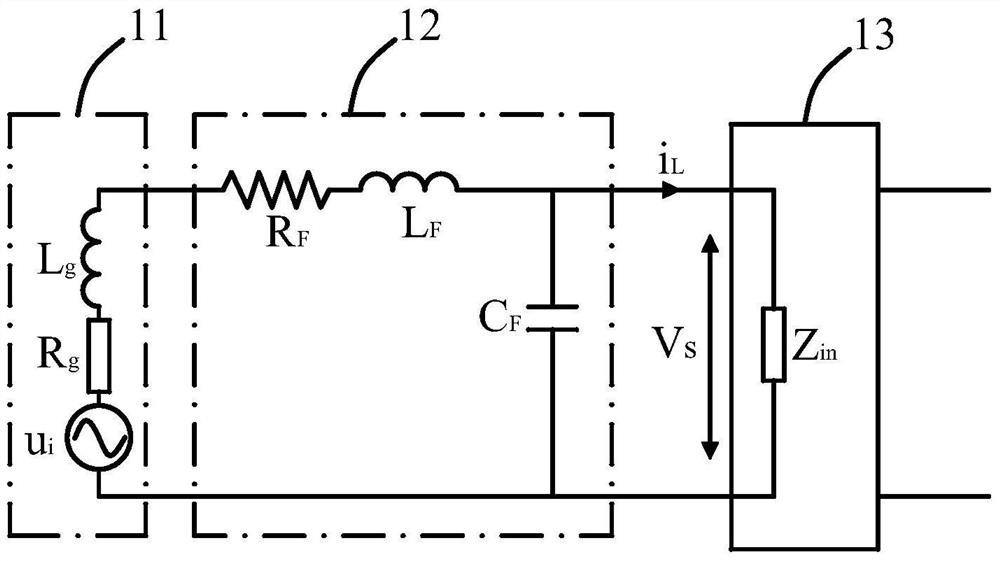
[0042] In an uninterruptible power supply, a double closed-loop control system is usually used to control the power factor correction circuit 13, ie voltage outer loop control and current inner loop control. The power factor correction circuit 13 is controlled by the current loop controller, which can speed up the response speed of the voltage, and can perform current limiting and protection when the current is too large.

[0043] refer again figure 1 , let the choke current value of the power factor correction circuit 13 be i L , the bus capacitor in the power factor correction circuit 13 ( figure 1 Not shown) The voltage value across both ends is u c , and the inductance ( figure 1 not shown) the inductance value is L, the transf...


PUM


Abstract

The present invention provides a power factor correction control method and control device for an uninterruptible power supply. The uninterruptible power supply includes a power factor correction circuit and a current loop controller for controlling the power factor correction circuit. The power factor correction The control method includes the following steps: 1) calculating the input voltage difference of the input voltage of the power factor correction circuit in two time periods; 2) comparing the input voltage difference with a predetermined first threshold; 3) according to The comparison result of step 2) adjusts the gain of the current loop controller. The power factor correction control method of the invention can make the power factor correction circuit adapt to different AC input power sources and work stably.

Description

technical field [0001] The invention relates to the control field of an uninterruptible power supply, in particular to a power factor correction control method and a control device of the uninterruptible power supply. Background technique [0002] figure 1 is the equivalent model diagram of the uninterruptible power supply system in the prior art, such as figure 1 As shown, the AC input power source 11 is connected to the input terminal of the power factor correction circuit 13 through the electromagnetic interference filter 12 . [0003] refer to figure 1 As shown, it is assumed that the input voltage value of the AC input power supply 11 is u i , the values ​​of the equivalent resistance and equivalent inductance in series are R g , L g , then its equivalent impedance value Z g =R g +L g s, s is the complex frequency domain. The values ​​of the equivalent resistance and the equivalent inductance connected in series in the electromagnetic interference filter 12 are...

Claims


Application Information

Patent Timeline
Patent Type & Authority Patents(China)
IPC IPC(8): H02M1/42
CPCH02M1/4208Y02B70/10Y02P80/10
Inventor 任晓丽杨国权谢亚红
Owner EATON MFG LP GLASGOW SUCCURSALE DE MOR
Why Eureka
Try Eureka