
Method and computer-based tool for composite-structure fabrication design

Inactive Publication Date: 2015-05-21
COLLIER RES & DEV
View PDF9 Cites 7 Cited by
  • Summary
  • Abstract
  • Description
  • Claims
  • Application Information

AI Technical Summary

Benefits of technology

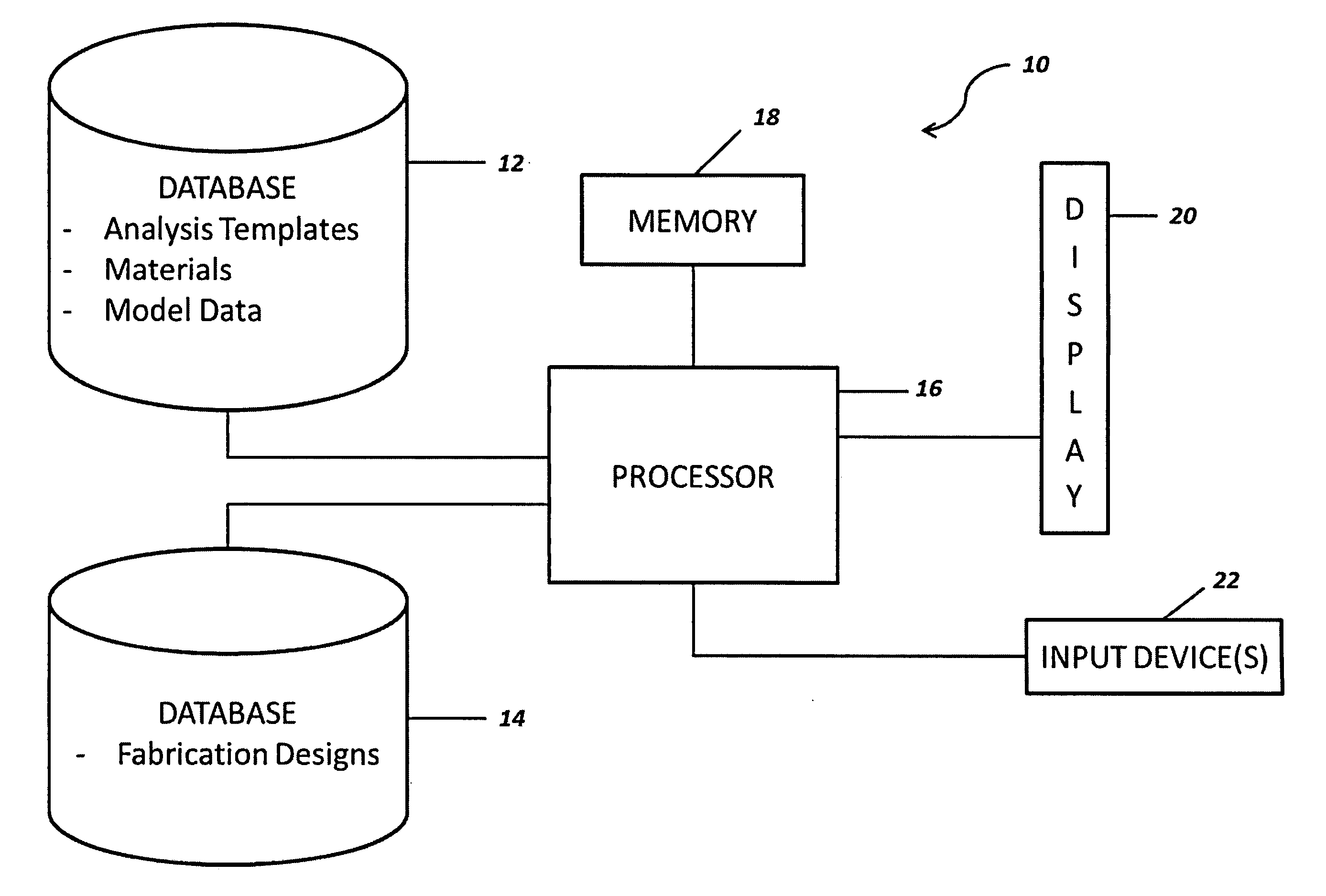
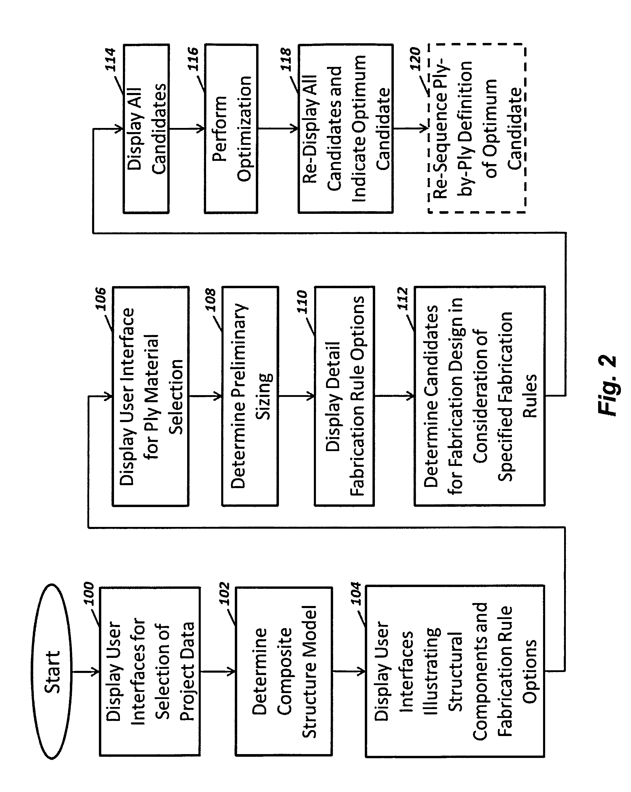
The present invention provides a computer system and method for designing the fabrication of composite structures. The computer system includes a database for storing data, a memory device for storing a computer program, a display device for generating visual images, an input device for receiving user selections, and a processor for executing the computer program. The computer system allows users to select from various data options to create a composite structure model, select fabrication rules for the model, and view different ply-by-ply definitions of how the structure can be fabricated. An optimization routine is then performed to choose the best option for fabrication. The system also allows for the real-time visual indication of the chosen option. Overall, the invention streamlines the design process for composite structures and improves efficiency.

Problems solved by technology

This lengthens the overall design process and ultimately increases the costs associated therewith since the end product does not satisfy other needs and thus requires manual or “by hand” method iterations in order to properly account for all the concerns of the end user.

Method used


Image

  • Method and computer-based tool for composite-structure fabrication design
  • Method and computer-based tool for composite-structure fabrication design
  • Method and computer-based tool for composite-structure fabrication design

Examples


Embodiment Construction

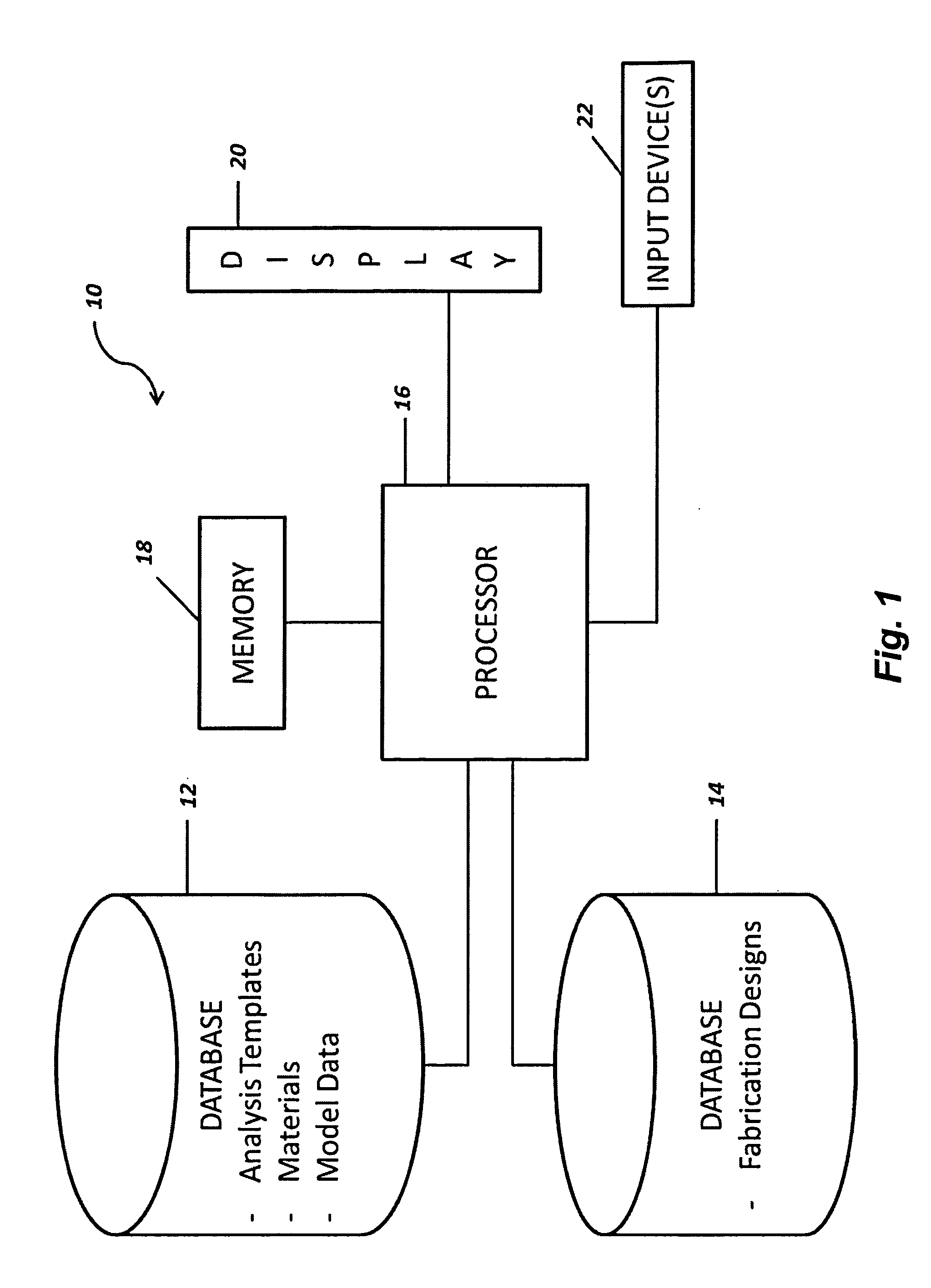
[0033]Referring now to the drawings and more particularly to FIG. 1, a computer system 10 is shown that is configured for the generation of a composite-structure fabrication design in accordance with an embodiment of the present invention. As used herein, the term “composite structure” refers to a multiple-ply laminate skin(s) supported on / by multiple-ply laminate longerons / stiffeners. The term “fabrication design” refers to a computer-aided design for a composite structure that has been optimized in terms of generic structural criteria as well as being optimized in terms of a variety of particular fabrication rules that are selected by a designer during the design process. That is and as will be explained further below, the present invention streamlines composite structure design by presenting a plurality of user interfaces that allow a user / designer to specify a variety of fabrication rules in an easy-to-access and logical fashion. Generic structural criteria and user selections f...


PUM


Abstract

A computer system and method are provided for generating a composite-structure fabrication design. During execution of the method on the computer system, a plurality of user interfaces prompt a user to enter generic design criteria as well as specific fabrication rules. Both generic design criteria and specified fabrication rules are considered simultaneously when determining candidates for fabrication designs. An optimization routine applied to the candidates yields an optimum fabrication design.

Description

FIELD OF THE INVENTION[0001]The invention relates generally to composite structure design, and more particularly to a method and computer-based tool to include user interfaces that facilitate development of a fabrication design for a composite structure.BACKGROUND OF THE INVENTION[0002]A wide variety of commercially-available computer-aided design products have been used for years to perform finite element analysis (FEA) routines and non-FEA routines in order to solve the problem of structure optimization. In terms of composite structures, these design products allow a user / designer to evaluate a large number of potential problem solutions (e.g., ply counts and ply orientation for a laminate-based composite structure) along with analysis to provide an optimum solution. For example, one such design product known as HYPERSIZER has been commercially-available since 1996 from Collier Research and Development Corporation, Hampton, Va. An end user or fabricator using these conventional de...

Claims


Application Information

Patent Timeline
IPC IPC(8): G05B19/4097G06F17/50
CPCG06F17/50G05B19/4097G05B2219/35113G06F30/15G06F30/00
Inventor COLLIER, CRAIG SHELTONYARRINGTON, PHILLIP WADEMAITIN, JOHN BENJAMINLUCKING, RYAN CHRISTOPHERAINSWORTH, III, JAMES JOSEPH
Owner COLLIER RES & DEV
Learn More