
Control system for stabilizing a floating wind turbine

a control system and wind turbine technology, applied in the direction of machines/engines, mechanical equipment, transportation and packaging, etc., can solve the problems of increasing costs, large conservatism, and reducing damages of floating wind turbines

Pending Publication Date: 2022-10-13
SIEMENS GAMESA RENEWABLE ENERGY AS
View PDF0 Cites 0 Cited by
  • Summary
  • Abstract
  • Description
  • Claims
  • Application Information

AI Technical Summary

Benefits of technology

The patent describes a control system for a floating wind turbine that can adjust its position to match a pre-defined angle, making it more stable. This system can also use data from wind and wave forecasts to optimize power output. By using a modular design and changing the natural frequency of the turbine, it can reduce loads and improve performance. The technical effects of this patent are that it can improve the stability and efficiency of floating wind turbines and reduce costs in the production line.

Problems solved by technology

Additionally, in the today's offshore industry there exists a large conservatism due to many uncertainties regarding the influence of wind loads and wave loads on the overall global system of the floating wind turbine and due to safety issues.
Furthermore, to avoid any possible overlap between frequencies of environmental loads and the global natural frequency of the floating wind turbine at given environmental conditions, conservatism is put into the today's design process of the floating wind turbine, which ends up in increasing costs.
Additionally, damages of the floating wind turbine may be decreased and therefore a durability may be elongated.
Particularly isolated manipulating of the pitch of the floating wind turbine may result in a fast tilting along the floater pitch.
Particularly, the actuator may increase / decrease the draught and thereby increases / decrease the stiffness of the floating wind turbine.
This may streamline design and production and lower costs in the production line.

Method used


Image

  • Control system for stabilizing a floating wind turbine
  • Control system for stabilizing a floating wind turbine
  • Control system for stabilizing a floating wind turbine

Examples


Embodiment Construction

[0081]The illustration in the drawing is schematic. It is noted that in different figures, similar or identical elements or features are provided with the same reference signs or with reference signs, which are different from the corresponding reference signs only within the first digit. To avoid unnecessary repetitions elements or features which have already been elucidated with respect to a previously described embodiment are not elucidated again at a later position of the description.

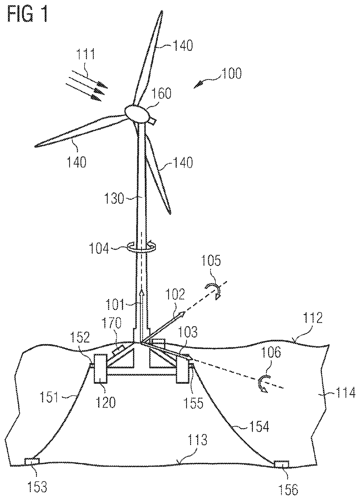
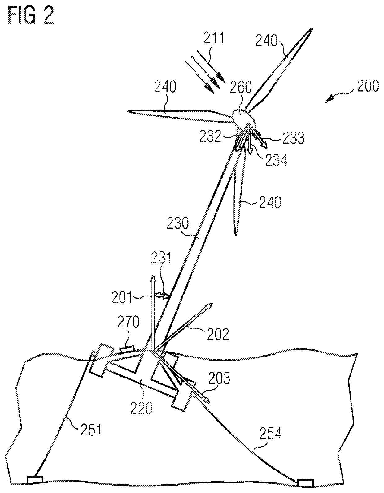
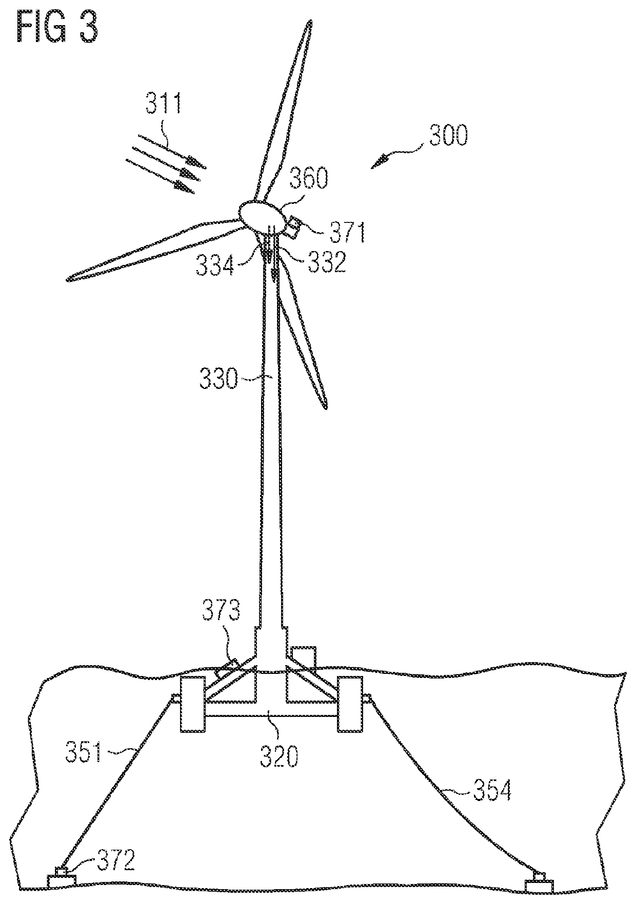
[0082]FIG. 1 shows a floating wind turbine 100 according to an exemplary embodiment of the present invention. The floating wind turbine 100 comprises three blades 140 attached to a hub mounted to a nacelle 160, a tower 130 and a floating foundation 120. The floating wind turbine 100 further comprises a plurality of mooring lines. Only a first mooring line 151 and a second mooring line 154 are shown in FIG. 1 for clarity reasons. The first mooring line 151 is fixed to the floating foundation 120 by a ...


PUM


Abstract

A control system for stabilizing a floating wind turbine is provided. The control system includes a measuring device configured for measuring a wind field and a wave field, a determining device wherein the determining device is configured for determining an excitation frequency spectrum of the floating wind turbine on the basis of the measured wind field and / or the wave field and / or a current floater pitch angle of the floating wind turbine, and wherein the determining device is further configured for determining a balanced state of the floating wind turbine, wherein in the balanced state a natural frequency is outside of the excitation frequency spectrum and / or the current floater pitch angle is equal to a pre-defined floater pitch angle. The control system further includes an adjustment device which is configured for manipulating the current floater pitch and / or the natural frequency until the balanced state is met.

Description

CROSS-REFERENCE TO RELATED APPLICATIONS[0001]This application claims priority to PCT Application No. PCT / EP2020 / 070994, having a filing date of Jul. 24, 2020, which claims priority to EP Application No. 19192450.5, having a filing date of Aug. 20, 2019, the entire contents both of which are hereby incorporated by reference.FIELD OF TECHNOLOGY[0002]The following relates to a control system for stabilizing a floating wind turbine. Further, the following relates to a floating wind turbine and a method for stabilizing a floating wind turbine.BACKGROUND[0003]In the technical field of floating wind turbines, it is known that floating wind turbines are designed such that the frequencies of the overall global system, particularly of the floating wind turbine comprising a rotor-nacelle assembly, a tower and a floating foundation, do not overlap with frequencies of environmental loads, i.e., the frequencies of the environmental influences to the floating wind turbine, particularly forces from...

Claims


Application Information

Patent Timeline
Patent Type & Authority Applications(United States)
IPC IPC(8): F03D13/25F03D7/02B63B39/03B63B39/14B63B43/06B63B35/44
CPCF03D13/25F03D7/0296B63B39/03B63B39/14B63B43/06B63B35/44F05B2240/93F05B2240/97B63B2035/446F03D17/00F03D80/00B63B39/00Y02E10/72Y02E10/727
Inventor ESBENSEN, THOMASLAUGESEN, KASPER
Owner SIEMENS GAMESA RENEWABLE ENERGY AS
Learn More