Motion analyzing method and motion analyzing apparatus

Inactive Publication Date: 2015-05-21
SEIKO EPSON CORP
View PDF3 Cites 15 Cited by
  • Summary
  • Abstract
  • Description
  • Claims
  • Application Information

AI Technical Summary

Benefits of technology

[0007]An advantage of some aspects of the invention is to solve at least a part of the problems de

Problems solved by technology

However, according to the method of displaying the analysis information with two axes as described above, it is difficult to cross-check the point of the swing motion and the analysis result in time series at a glance.
For exa

Method used


Image

  • Motion analyzing method and motion analyzing apparatus
  • Motion analyzing method and motion analyzing apparatus
  • Motion analyzing method and motion analyzing apparatus

Examples


first embodiment

[0036]As below, a golf swing analyzing apparatus (motion analyzing apparatus) and a golf swing analyzing method (motion analyzing method) according to the invention will be explained with reference to the drawings. The golf swing analyzing method (motion analyzing method) will be explained in conjunction with the explanation of the golf swing analyzing apparatus (motion analyzing apparatus).

(1) Configuration of Golf Swing Analyzing Apparatus

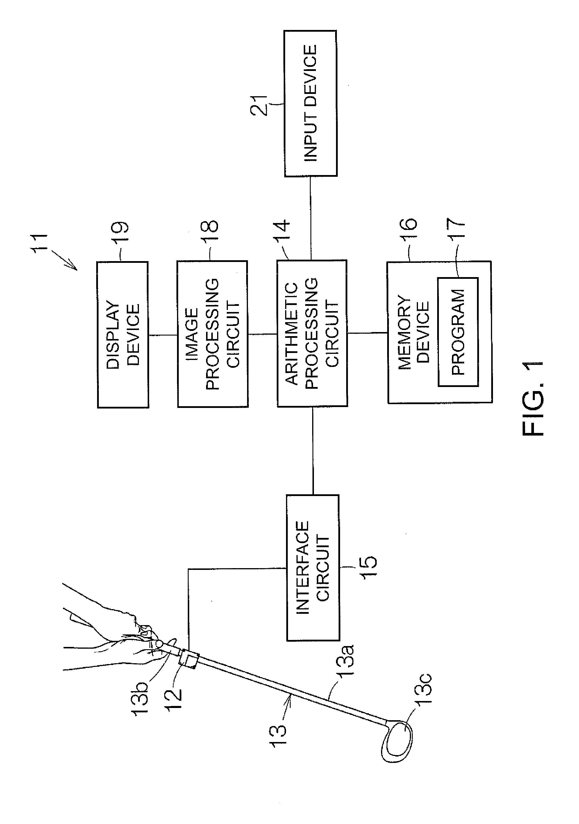
[0037]A configuration of the golf swing analyzing apparatus (motion analyzing apparatus) according to the embodiment of the invention is explained with reference to FIG. 1. FIG. 1 schematically shows a configuration of a golf swing analyzing apparatus (motion analyzing apparatus) 11 according to the embodiment of the invention. The golf swing analyzing apparatus 11 includes, e.g., an inertial sensor 12. For example, an acceleration sensor and a gyro sensor are incorporated in the inertial sensor 12. The acceleration sensor can detect acceleration...

second embodiment

[0076]In the above described first embodiment, in the analysis information calculation part 39, the energy change rate indicating the energy state generated between the subject and the golf club 13 from the initial state at the angle “0°” and during swing according to the time axis based on the output of the inertial sensor 12 has been explained as an example. In the second embodiment, in the analysis information calculation part 39, an example of outputting time-series changes of the relative rotation angle θn of the grip 13b during swing from the initial state at the angle “0°” based on the output of the inertial sensor 12 is explained using FIGS. 6 and 7. FIG. 6 shows one specific example of a graph showing changes of the relative rotation angle θ according to the time axis in which the time axis [ms] is set on the horizontal axis and the relative rotation angle θn [deg] is set on the vertical axis. Note that, with respect to a threshold value L2 in FIG. 6, the relative rotation ...

third embodiment

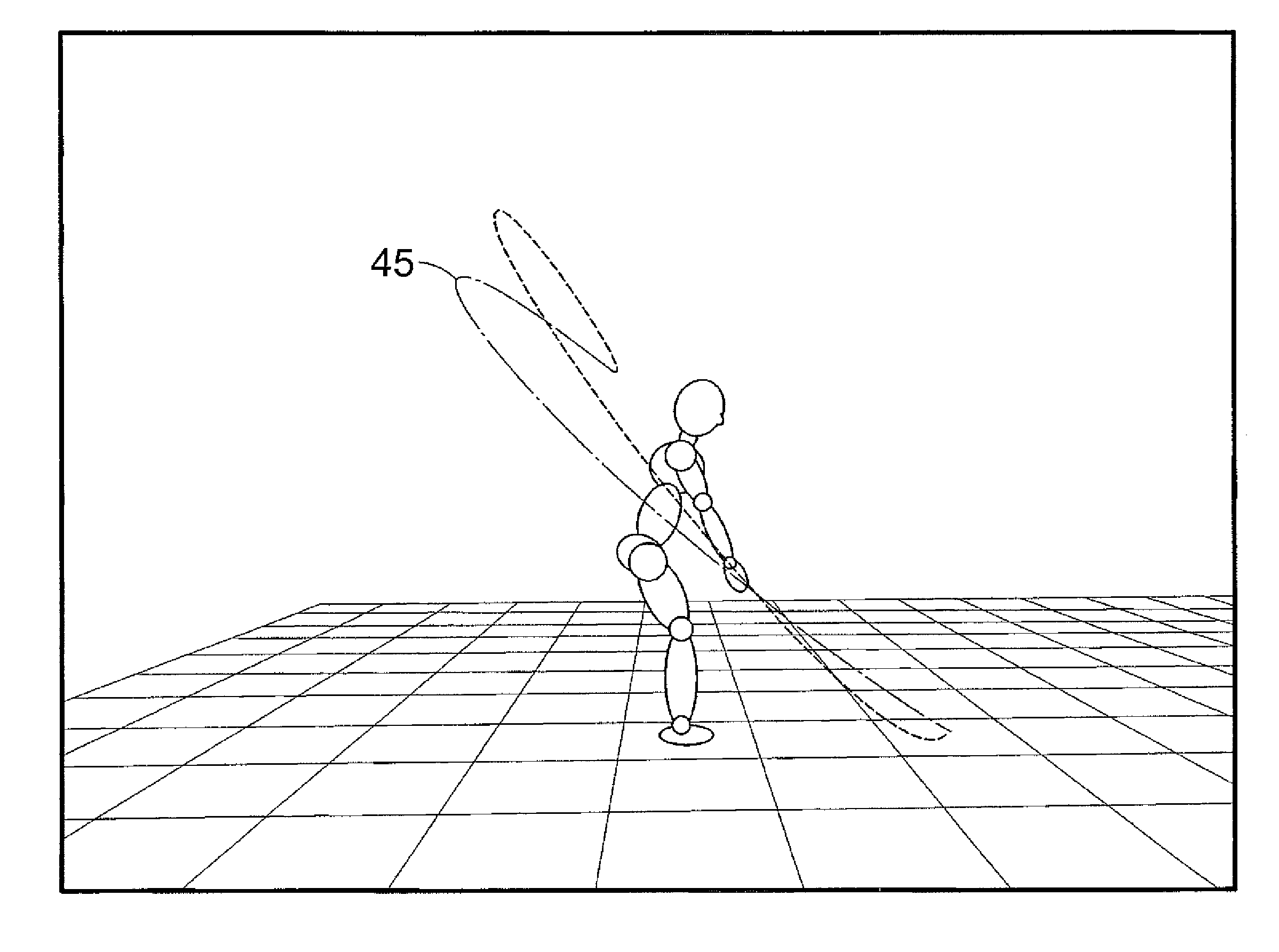
[0082]In the above described first embodiment, the example in which the energy change rates (trend) in swing motion are drawn by gradation display in the pseudo circular graph in the nearly semi-circle shape drawn on the movement trace (swing trace) of the golf club 13 has been explained, however, the drawing is not limited to that. In the third embodiment, the energy change rates (trend) are drawn by a line graph in the pseudo circular graph Gr in the nearly semi-circle shape drawn on the movement trace (swing trace) of the golf club 13 in place of the gradation display. As below, the third embodiment will be explained using FIG. 8. FIG. 8 shows one specific example of a pseudo circular graph that correlates the changes of the energy change rate with the swing path trace according to the third embodiment. The same configurations as those of the above described first embodiment have the same signs and their explanation is omitted.

[0083]The motion analyzing method according to the th...


PUM


Abstract

A motion analyzing method includes: acquiring location information of at least one of a sporting tool and a subject in swing motion based on an inertial force generated by the swing motion in time series; acquiring analysis information of the swing motion based on the inertial force; acquiring a time when the analysis information is switched with respect to a preset threshold value; and correlating information of the time with the location information and outputting the information.

Description

CROSS REFERENCE[0001]The entire disclose of Japanese Patent Application No. 2013-236598, filed Nov. 15, 2013, is expressly incorporated by reference herein.BACKGROUND[0002]1. Technical Field[0003]The present invention relates to a motion analyzing method and a motion analyzing apparatus.[0004]2. Related Art[0005]A motion analyzing apparatus is used for analysis of motion including swing motion. The position of a sporting tool at swing changes over time. The swing motion is visually reproduced by trace display of a swing path or the like based on the output of an inertial sensor attached to the sporting tool or a hand. As one specific example of the motion analyzing apparatus, for example, there is an example disclosed in Patent Document 1 (JP-A-2011-142927). In this example, swing trace information and an analysis result are separately displayed as disclosed in FIG. 12 of Patent Document 1, and the analysis result is displayed with two axes of “time on horizontal axis” and “analysis...

Claims


Application Information

Patent Timeline
IPC IPC(8): G01B21/00A63B24/00G01P15/00
CPCG01B21/00A63B24/0006G01P15/00G09B19/0038A61B5/6895A63B69/3608A63B2071/0647A63B2220/40A63B2220/51A63B2220/833A61B5/1122A61B2503/10A61B2505/09
Inventor SHIBUYA, KAZUHIRO
Owner SEIKO EPSON CORP
Why Eureka
Try Eureka