Electrical connector having an improved structure for assembling a contact module to an insulative housing

Active Publication Date: 2015-05-28
FOXCONN INTERCONNECT TECHNOLOGY LIMITED
View PDF52 Cites 9 Cited by
  • Summary
  • Abstract
  • Description
  • Claims
  • Application Information

AI Technical Summary

Benefits of technology

[0008]Accordingly, an object of the present invention is to provide an electrical connect

Problems solved by technology

The top and front wedges are separated too far apart that it is difficult to mount the contact module to the insulative housing.
After the assembling process, the contact module may

Method used


Image

  • Electrical connector having an improved structure for assembling a contact module to an insulative housing
  • Electrical connector having an improved structure for assembling a contact module to an insulative housing
  • Electrical connector having an improved structure for assembling a contact module to an insulative housing

Examples


Embodiment Construction

[0016]Reference will now be made in detail to the preferred embodiment of the present invention.

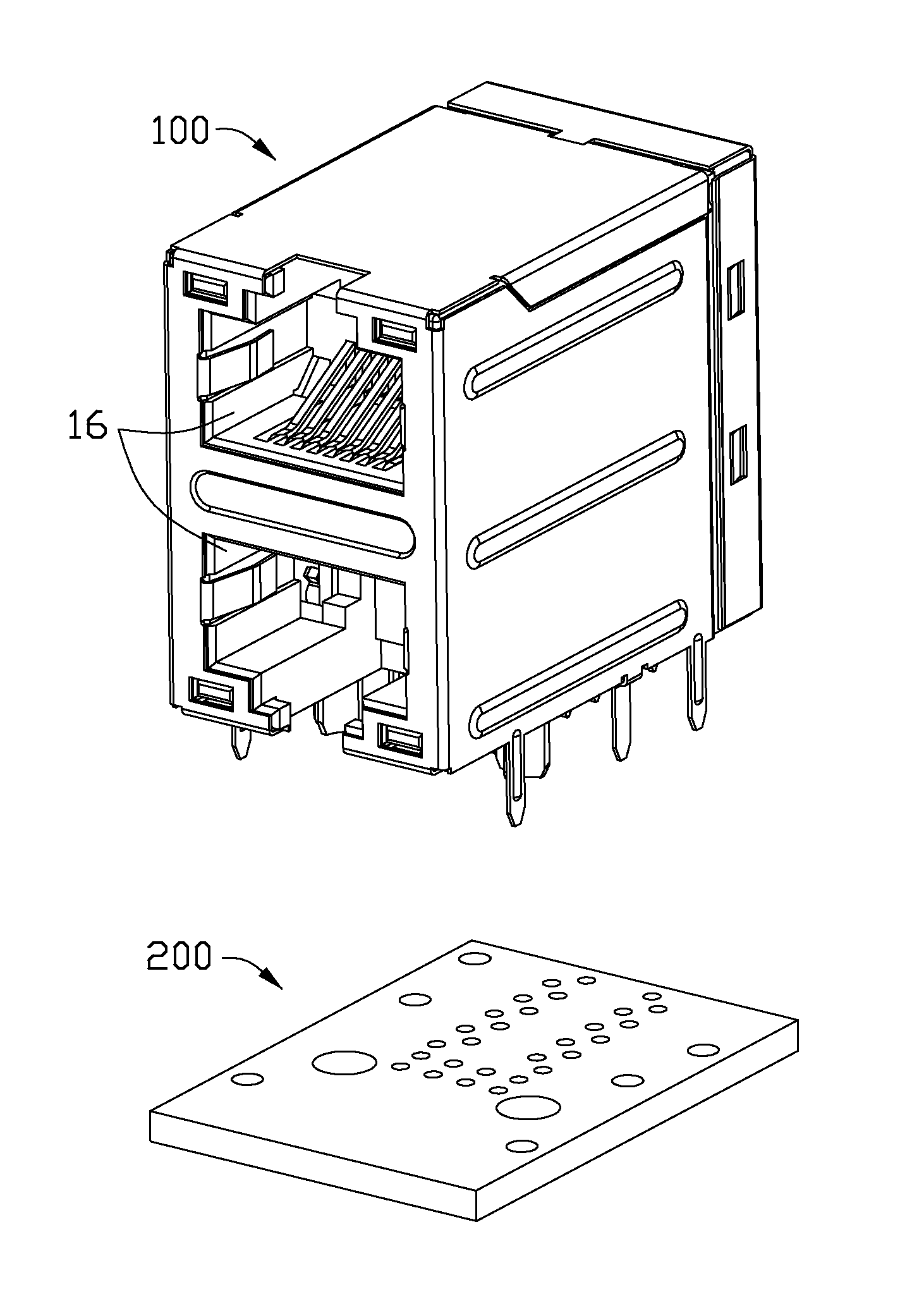
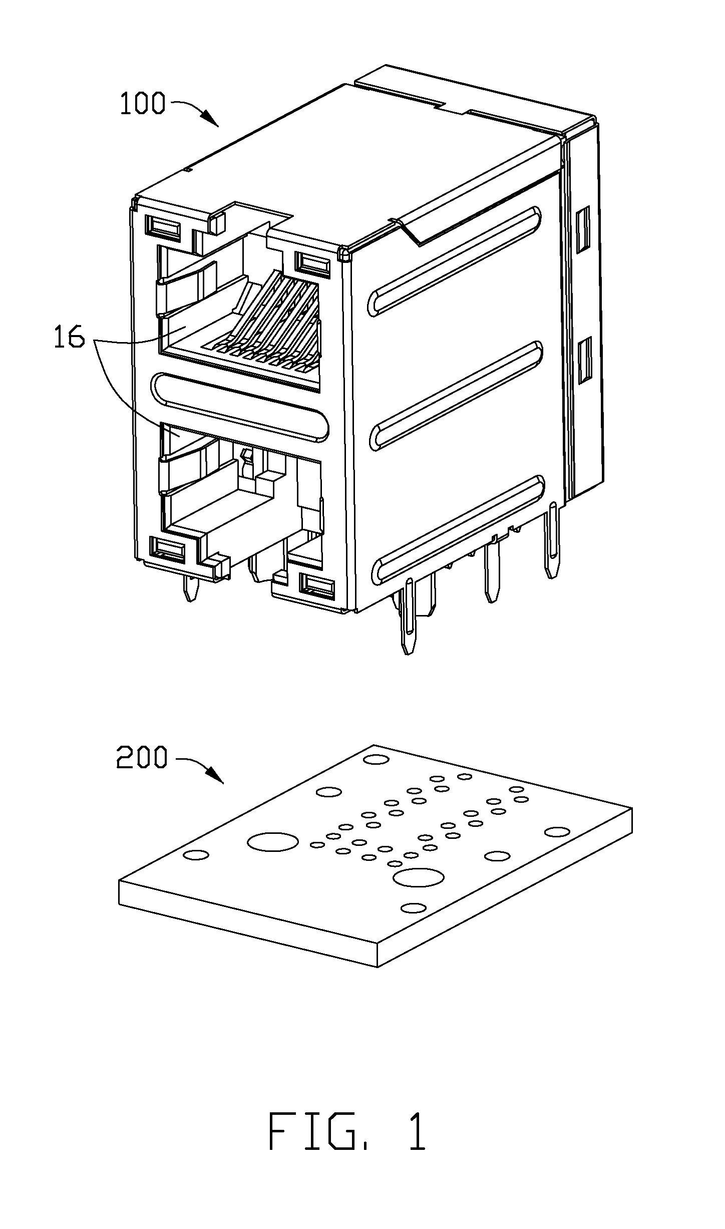
[0017]Referring to FIGS. 1-5, an electrical connector 100 according to the present invention is shown. The electrical connector 100 could be mounted on a horizontal mother PCB 200.

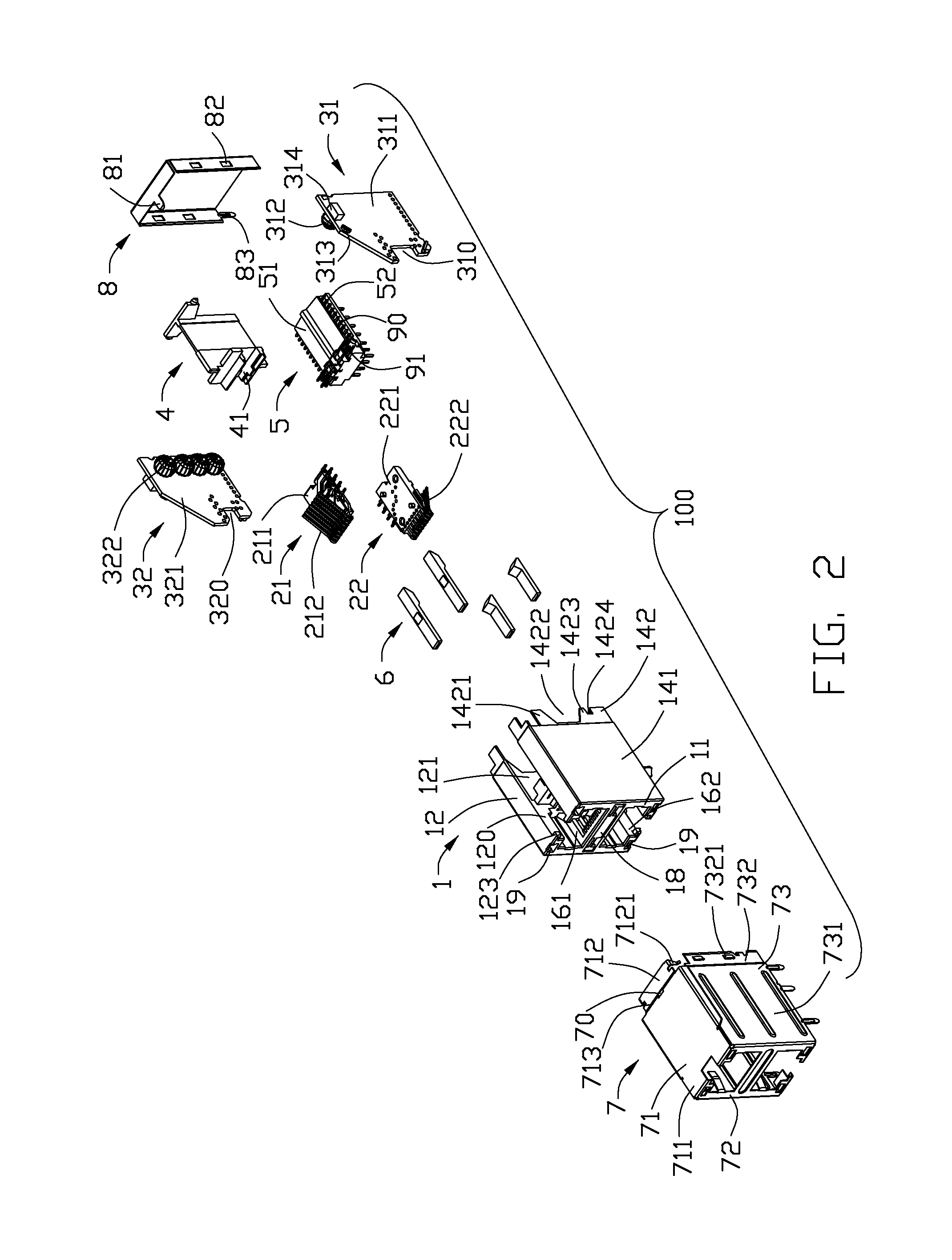
[0018]Referring to FIG. 2, the electrical connector 100 includes an insulative housing 1, a lower mating contact module 22, an upper mating contact module 21, a first vertical PCBA (printed circuit board assembly) 31, a second vertical PCBA 32, a middle bracket 4, a mounting contact module 5, a plurality of light pipes 6, a front shielding shell 7, and a rear shielding shell 8.

[0019]Referring to FIGS. 2-3, the insulative housing 1 has a front wall 11, a top wall 12, a bottom wall 13, an intermediate wall 18, two side walls 14, and a middle wall 15 disposed between the side walls 14 and perpendicular to the intermediate wall 18. The insulative housing 1 defines a lower receiving cavity 162 located below the inter...


PUM


Abstract

An electrical connector includes an insulative housing, a lower mating contact module, and an upper mating contact module. The insulative housing has a lower receiving cavity, an upper receiving cavity, and an intermediate wall located therebetween. The lower mating contact module has a lower insulating carrier and a set of lower mating contacts secured to the lower insulating carrier. The upper mating contact module has an upper insulating carrier and a set of upper mating contacts secured to the upper insulating carrier. The intermediate wall defines a lower passageway extending along a front-to-back direction and an upper passageway disposed above the lower passageway. The lower insulating carrier has a lower fixing arm inserted and fixed in the lower passageway, and the upper insulating carrier has an upper fixing arm inserted and fixing in the upper passageway.

Description

BACKGROUND OF THE INVENTION[0001]1. Field of the Invention[0002]The present invention relates to an electrical connector having a contact module and an insulative housing, and more particularly to a structure for fixing the contact module to the insulative housing.[0003]2. Description of Related Art[0004]U.S. Pat. No. 7,736,176, issued on Jun. 15, 2010, discloses an electrical connector including an insulative housing, a contact module mounted to the insulative housing, and a shielding shell enclosing the insulative housing and the contact module. The contact module has a mating contact module, a center bracket, a first vertical PCB mounted to a side of the center bracket, a second vertical PCB mounted to an opposite side of the center bracket, and a mounting contact module connecting with bottoms of the vertical PCBs. The mating contact module has an insulating carrier, a set of upper mating contacts, and a set of lower mating contacts. The upper and lower mating contacts are secur...

Claims


Application Information

Patent Timeline
IPC IPC(8): H01R25/00H01R12/75H01R12/70
CPCH01R25/006H01R12/75H01R12/7082H01R12/716H01R13/514H01R13/6466H01R13/6594H01R13/7175H01R24/64H01R2201/04
Inventor GAO, SHENG-PINZHANG, DAO-KUANHSU, CHIH-CHING
Owner FOXCONN INTERCONNECT TECHNOLOGY LIMITED
Why Eureka
Try Eureka