
Analysis system and method thereof

a technology of an analysis system and a method, applied in the field of an analysis system, can solve the problems of inability to know individual overall trend toward and change physiological parameters, inability to collate information for each time in a systematic way, and inability to effectively get their physical condition and related information

Inactive Publication Date: 2015-06-11
NAT CENT UNIV
View PDF11 Cites 1 Cited by
  • Summary
  • Abstract
  • Description
  • Claims
  • Application Information

AI Technical Summary

Benefits of technology

The analysis system and method described in this patent is an automated health management system that uses data from personal health detectors to analyze health indicators and provide users with their physical condition information. The system measures and compares indicators to health indicators, and uses advanced techniques to analyze complex signals. The system can provide users with real-time information and track changes in their physiological parameters over time. Overall, this technology helps users better understand their overall health and make informed decisions about their well-being.

Problems solved by technology

However, the physiological signals detected by the detectors are various and complex, and the information measured for each time cannot be collated in a systematic way.
The users only can know the current physical condition, but cannot know individual overall trend toward and changes physiological parameters.
The conventional health management systems are not only relatively large and complex, but also need professional human operations to analyze, so the cost is high and it requires more manpower and time consuming.

Method used


Image

  • Analysis system and method thereof
  • Analysis system and method thereof
  • Analysis system and method thereof

Examples


first embodiment

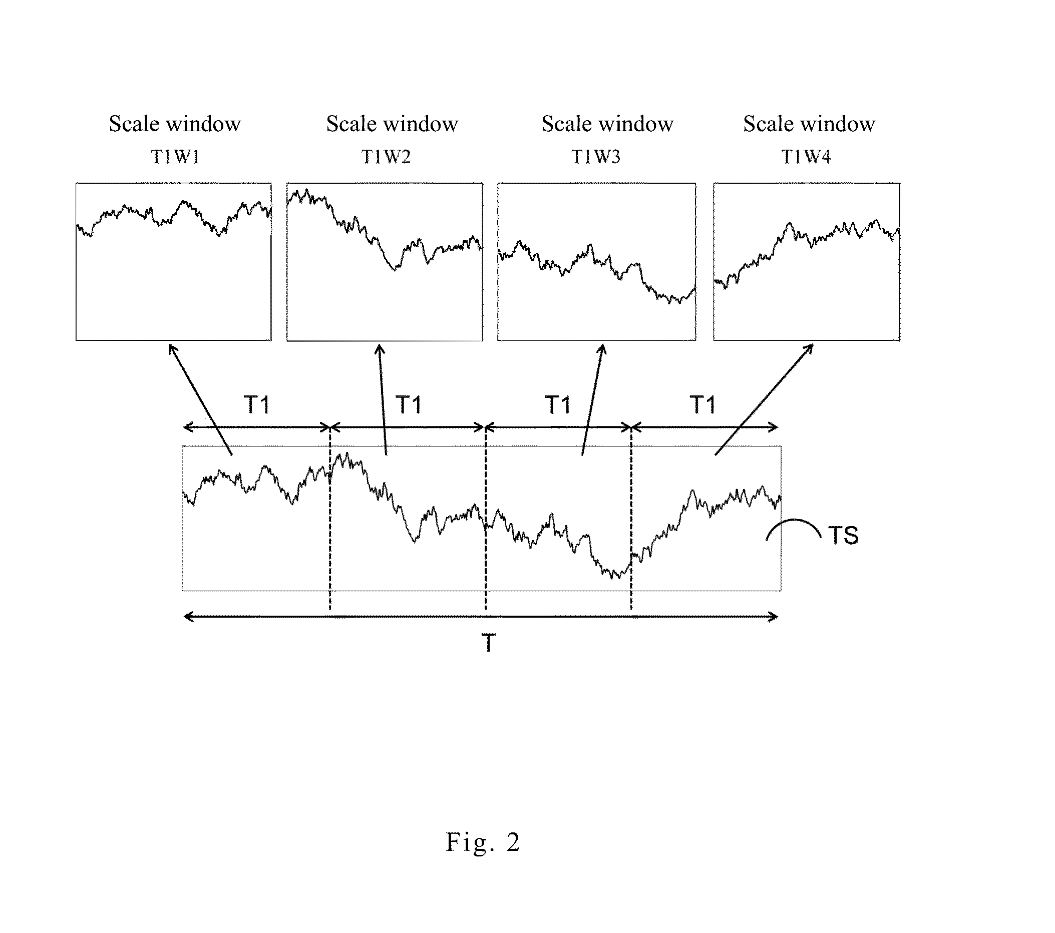
[0032]Please refer to FIG. 2 showing a diagram of the signal segmented in the invention. The segmenting unit 210 of the invention divides the time period T into a plurality of scale windows according to one of interval scales. The time period T can be divided by any one of different interval scales. In an embodiment, the interval scale is T1. When the time period T is 600 seconds and the interval scale is T1 is 20 seconds, the time period T is divided into 30 scale windows. When the interval scale is T1 is 40 seconds, the time period T is divided into 15 scale windows, which is not limited herein.

[0033]Please refer to FIG. 2, in order to clearly describe the features of the invention, the time period T being divided into 4 scale windows by the interval scale T1 is taken as an example. The 4 scale windows are respectively a scale window T1W1, a scale window T1W2, a scale window T1W3 and a scale window T1W4, which is not limited herein.

[0034]The analyzing unit 220 of the invention pro...

second embodiment

[0038]In another embodiment, please refer to FIG. 5 showing a diagram of the signal segmented in the invention. The segmenting unit 210 dividing the time period T into 6 scale windows by the interval scale T2 is taken as an example. The 6 scale windows are respectively a scale window T2W1, a scale window T2W2, a scale window T2W3, a scale window T2W4, a scale window T2W5, and a scale window T2W6, which is not limited herein.

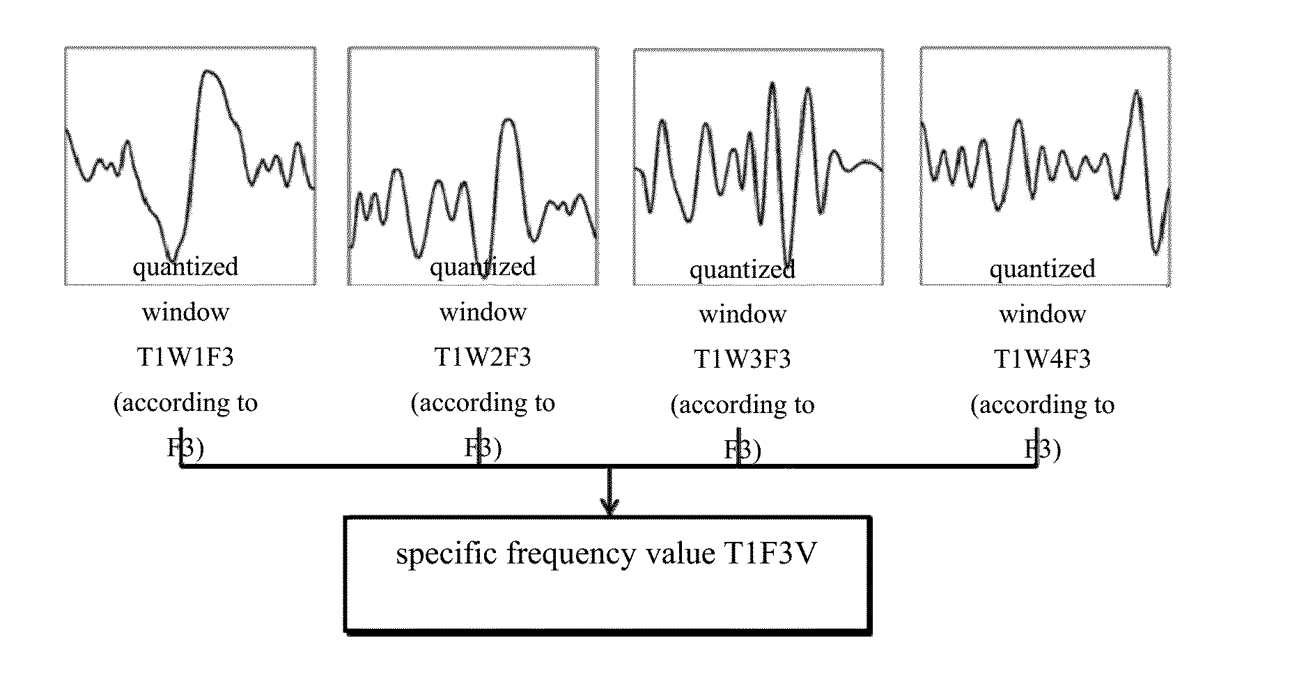
[0039]The analyzing unit 220 processes the scale window T2W1, the scale window T2W2, the scale window T2W3, the scale window T2W4, the scale window T2W5, and the scale window T2W6 to generate the quantized windows (T2W1F1, T2W1F2, T2W1F3, T2W1F4; T2W2F1, T2W2F2, T2W2F3, T2W2F4; T2W3F1, T2W3F2, T2W3F3, T2W3F4; T2W4F1, T2W4F2, T2W4F3, T2W4F4; T2W5F1, T2W5F2, T2W5F3, T2W5F4; T2W6F1, T2W6F2, T2W6F3, T2W6F4) respectively according to the first component F1, the second component F2, the third component F3, and the fourth component F4, which is not limited herein.

[0040]...


PUM


Abstract

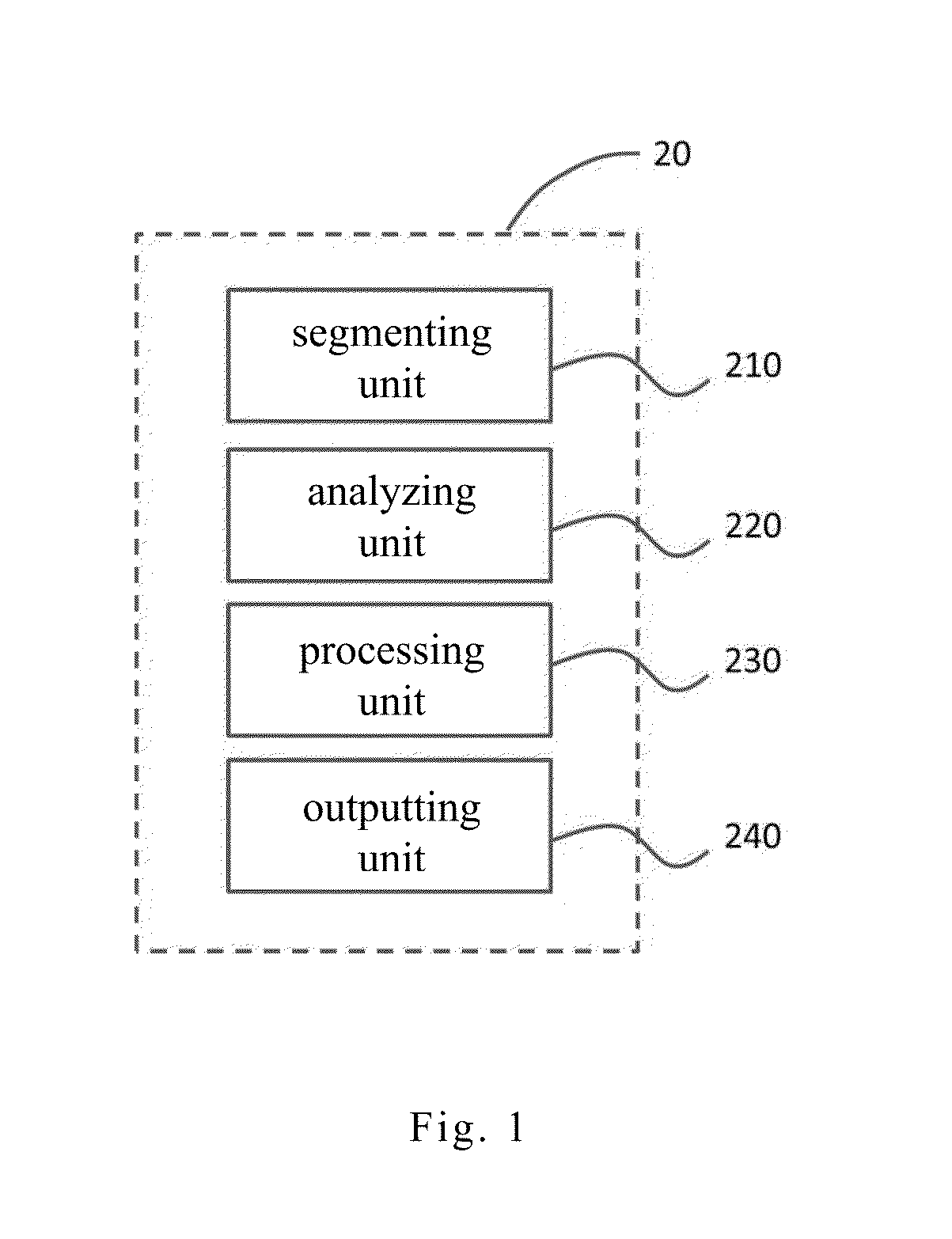
The present invention provides an analysis system adapted for processing a signal with a time period. The analysis system comprises a segmenting unit, an analyzing unit, processing unit and an outputting unit. The segmenting unit divides the signal into a plurality of scale windows according to one of interval scales. The analyzing unit processes the scale windows via HHT algorithm to make each scale window generate a plurality of quantized windows according to different components. The processing unit reorganizes the quantized windows make each scale window generate a plurality of quantized windows according to different components. The outputting unit accumulates a plurality of specific frequency values in difference interval scales and combines the specific frequency values to form a three-dimensional variation visual diagram.

Description

CROSS-REFERENCE TO RELATED APPLICATIONS[0001]This Non-provisional application claims priority under 35 U.S.C. §119(a) on Patent Application No(s). 102145345 filed in Taiwan, Republic of China on Dec. 10, 2013, the entire contents of which are hereby incorporated by reference.FIELD OF THE INVENTION[0002]The invention relates to an analysis system and, more particularly, to an analysis system can generate a three-dimensional variation visual diagram.BACKGROUND OF THE INVENTION[0003]As technology advances, more and more detectors are used to detect physiological signal, which can provide users detecting their physical condition by themselves. However, the physiological signals detected by the detectors are various and complex, and the information measured for each time cannot be collated in a systematic way. The users only can know the current physical condition, but cannot know individual overall trend toward and changes physiological parameters.[0004]The conventional technology has p...

Claims


Application Information

Patent Timeline
Patent Type & Authority Applications(United States)
IPC IPC(8): G10L19/00
CPCG10L19/00A61B5/02A61B5/7275G16H50/20
Inventor HUANG, NORDEN. E.KUO, BO-JAULIN, YU-CHENGPENG, CHUNG-KANGLO, MEN-TZUNG
Owner NAT CENT UNIV
Learn More