
System and Method for Payment Receipt Using 2D Code

payment receipt technology, applied in the field of system and method for payment receipt using a two-dimensional (2d) code, can solve the problems of information input errors, increased time and expense, etc., and achieve the effect of saving time and expense, reducing printing expenses, and effectively obtaining and sorting required information

Inactive Publication Date: 2008-09-18
DUZON DASS CO LTD
View PDF7 Cites 19 Cited by
  • Summary
  • Abstract
  • Description
  • Claims
  • Application Information

AI Technical Summary

Benefits of technology

[0047]In accordance with the above constructions of the present invention, when making out a bill for payment, a procedure of assigning an OCR code from an authorized institution, e.g. FTCI is eliminated so that a fee to be additionally paid to the FTCI can be saved. In addition, a bill for payment is transmitted by wireless, wire communication means, and did not use expensive OCR sheets and ink, so that imprinting expenses can be minimized.
[0048]Further, a procedure is eliminated, in which a financial institution provides FTCI with an OCR card after the payment by a payer, and the FTCI reads-out the OCR card and provides the decoded information on a payee, a payer and so on to the financial institution in return, so that the payment for goods or services can be provided to the payee as soon as possible.
[0049]Further, a bill for payment is transmitted using wireless, wire communication means, so that a payment receipt system and method can be provided which have little risk of misdelivery and spend delivery expenses to the minimum.
[0050]Further, a payee can effectively obtain and sort required information on a payer, thereby saving the time and expenses required for obtaining and sorting the information. Furthermore, payer information provided to a payee is directly inter-worked with a management program, thereby saving the time and expenses required for operating the management program.

Problems solved by technology

This method of direct input of various information into the management program makes the time and expense increased, and causes various problems such as information input errors.

Method used


Image

  • System and Method for Payment Receipt Using 2D Code
  • System and Method for Payment Receipt Using 2D Code
  • System and Method for Payment Receipt Using 2D Code

Examples


first embodiment

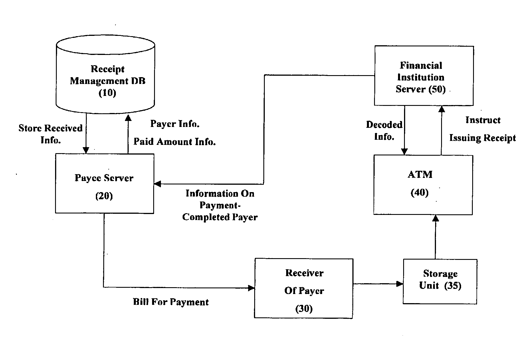
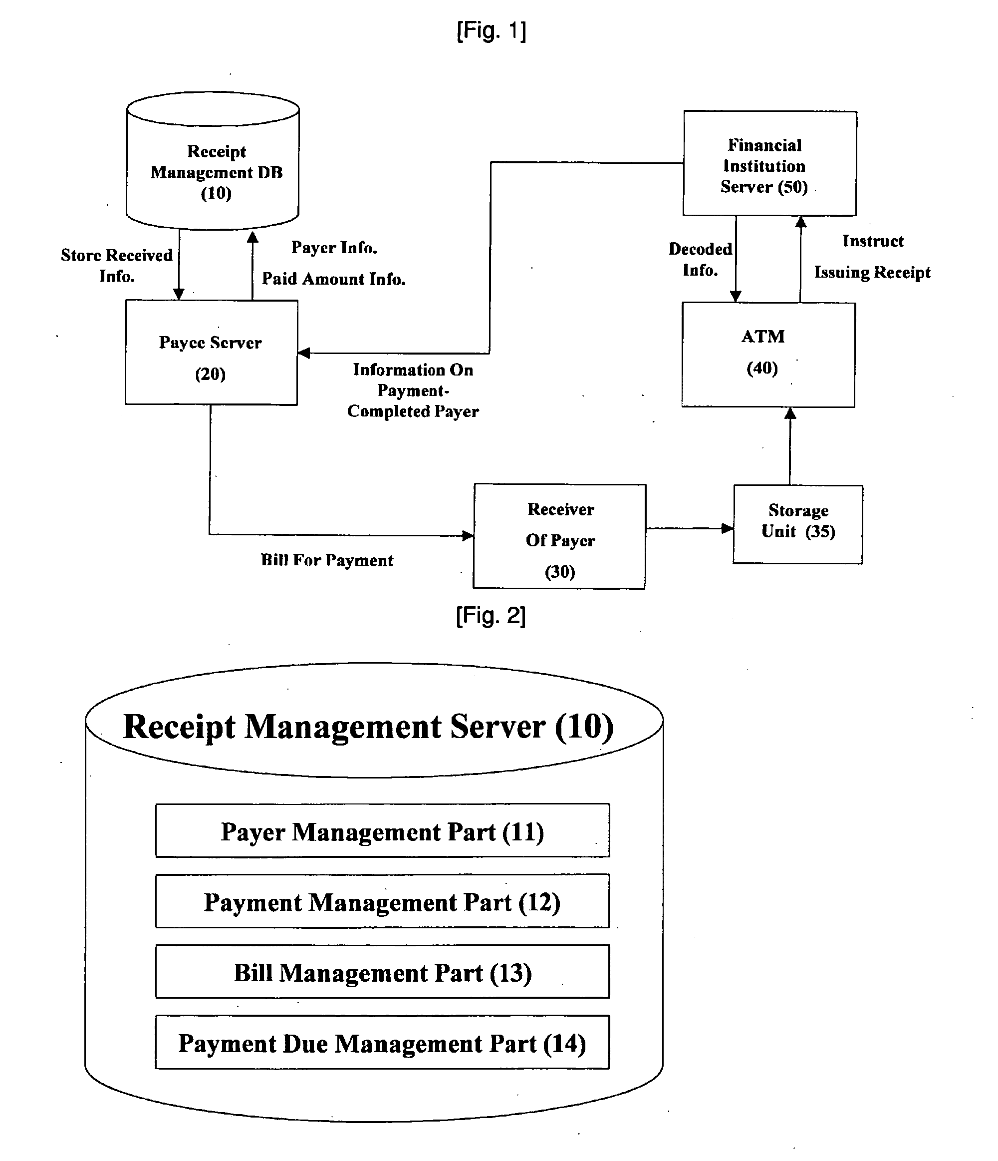
[0066]Next, the bill forming part 23 of the server 20 makes out a bill for payment onto which the 2D code formed from the code converting part 22 is attached. It is preferable that in addition to the 2D code converted by the above method, the bill for payment includes information on the payer, the payment amount, and the payment due in text type, in order for the payer to easily identify whether or not the bill for payment is concerned with him and how much amount is requested of him when he sees the bill for payment. Also, in order for the payer to recognize the bill for payment when transmitted to the receiver 30 of the payer via wireless, wire communication network, the bill for payment may be made out in a language suitable to a format applied to the receiver 30 of the payer, for example, html, xhtml, mhtml, shtml, wml, and so on, but the language is not limited thereto. In the first embodiment, although the bill for payment has been described to be provided to the payer in on-l...

second embodiment

[0085]FIG. 7 is a schematic block diagram illustrating a construction of a payment receipt system according to the present invention. In FIG. 7, like numerals refer to like parts in FIGS. 1 to 6, so that the detailed description thereof will be omitted.

[0086]As illustrated in FIG. 7, in the payment receipt system according to a second embodiment, the financial institution server 50 transmits information on payer, a payment amount, a payment due and so on to the relay server 60 after the settlement by the financial institution server 50. Then, the relay server 60 sorts the provided information and transmits the sorted information to the controller 25 of the payee server 20. Although information provided from the financial institution server 50 includes only basic personal information and a payment amount of the payer, the information may preferably include all recorded in the 2D code, and provide the controller with information in a state before or after decoding. The relay server 60...

third embodiment

[0087]FIG. 8 is a schematic block diagram illustrating a construction of a payment receipt system according to the present invention. In FIG. 8, like numerals refer to like parts in FIGS. 1 to 7, so that the detailed description thereof will be omitted.

[0088]Similar to the second embodiment, the payment receipt system illustrated in FIG. 8 includes a relay server 60 which receives information on payer, a payment amount, a payment due and so on, after the settlement by the financial institution server 50. Then, the relay server 60 sorts the provided information, and transmits the sorted information to the controller 25 of the payee server 20. In addition, the system further includes a management server 70. The management server 70 receives all of or a portion of various information on the payers provided from the financial institution server 50 to the relay server 60, re-processes the received information in information form that the payee wants to obtain, and transmits the re-proces...


PUM


Abstract

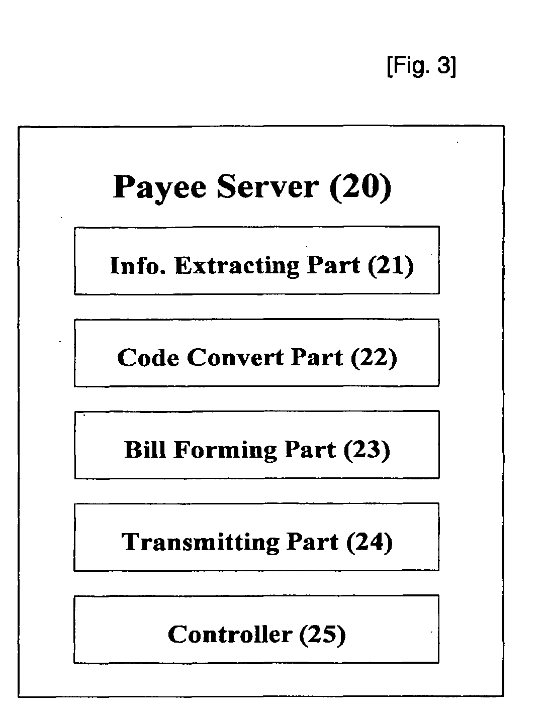
A payment receipt system is provided. The payment receipt system comprises: a receipt management database for managing at least information on the payers who have to pay and the payment amount that the respective payers have to pay for a certain period; and a payee server including an information extracting part for extracting information including the information on the payers and the payment amount from the receipt management database, a code converting part for converting the extracted information into a two-dimensional (2D) code, a bill forming part for making out a bill for payment with the converted 2D code attached thereto, a bill transmitting part for transmitting the bill for payment to a receiver of the payer, and a controller receiving information on the payers who have completed a payment from a financial institution server.

Description

TECHNICAL FIELD[0001]The present invention relates to a system and method for payment receipt using a two-dimensional (2D) code, and more particularly, to a system and method for payment receipt, capable of simplifying a settlement process using a bill where a 2D code storing certain information is imprinted.BACKGROUND ART[0002]Generally, the sellers or the service providers have used a billing method (hereinafter, referred to as “OCR method”) using an optical character recognition (OCR) card in order to ask the buyers or the service-beneficiaries to pay for the provision of material or immaterial goods, or services, such as electricity, service water, milk, newspaper, security, and so on. A process of the OCR method, in which the sellers or the service providers (hereinafter, referred to as “payee”), who provide goods or services, send a bill to the buyer or the service-beneficiaries (hereinafter, referred to as “payer”), who receive goods or services, and the payer pays for them, ...

Claims


Application Information

Patent Timeline
Patent Type & Authority Applications(United States)
IPC IPC(8): G06Q40/00
CPCG06Q30/04G06Q20/102G06Q40/02
Inventor KIM, YONG-WOOJEONG, HYE-JEONG
Owner DUZON DASS CO LTD
Learn More