
Decentralized control of motors

Inactive Publication Date: 2005-05-05
SEW-EURODRIVE GMBH & CO KG
View PDF5 Cites 18 Cited by
  • Summary
  • Abstract
  • Description
  • Claims
  • Application Information

AI Technical Summary

Benefits of technology

[0009] A more particular object of this invention is to provide a decentralized control system for group VFD installation that reduces the number of branch circuits which reduces implementation costs.
[0015] Another object of this invention is to provide a decentralized control system for group VFD installation that minimizes the amount of space required for occupation in conventional main control cabinets of cabling and components.
[0016] Another object of this invention is to provide a decentralized control system for group VFD installation that minimizes the cabling and component expense in comparison with conventional group VFD installations.
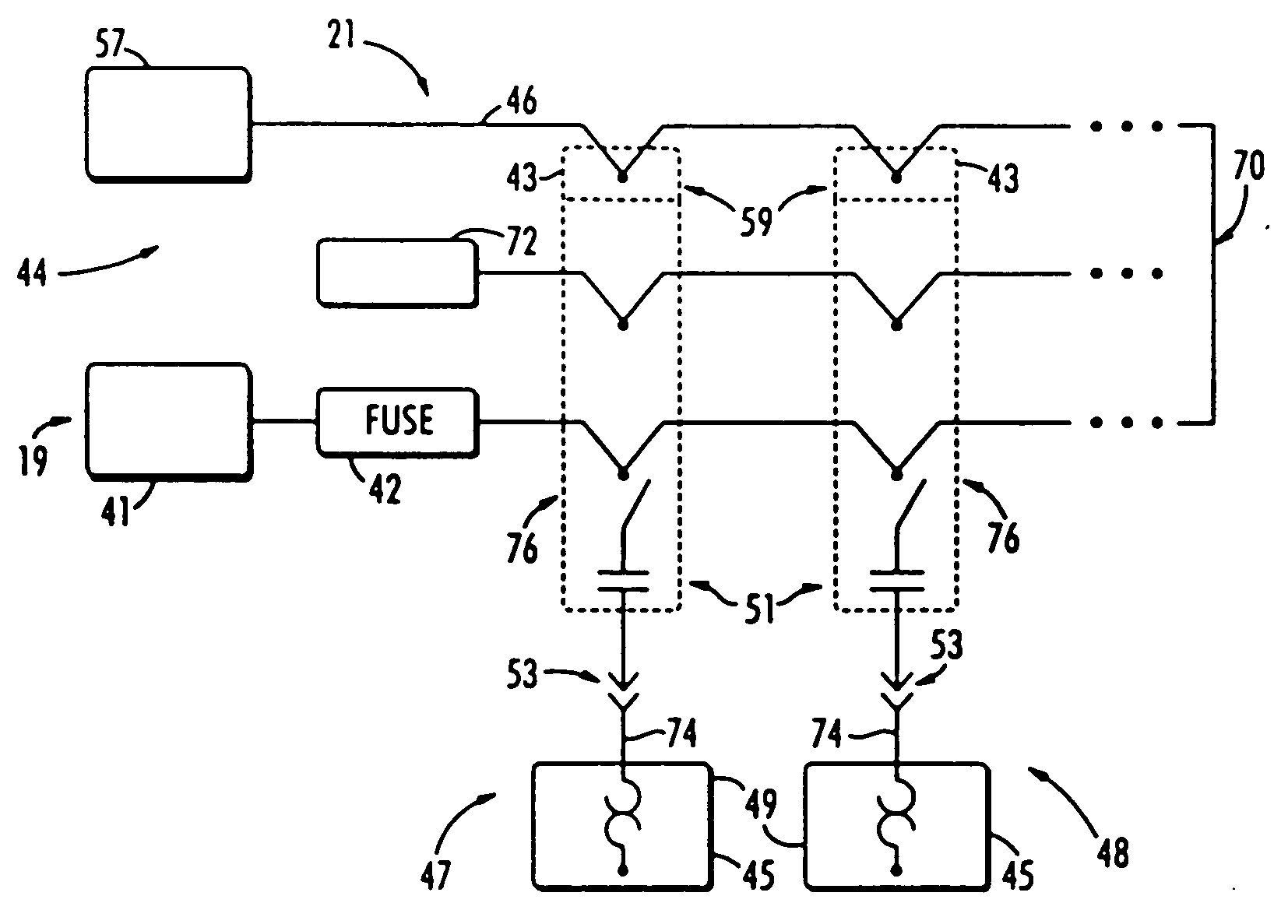
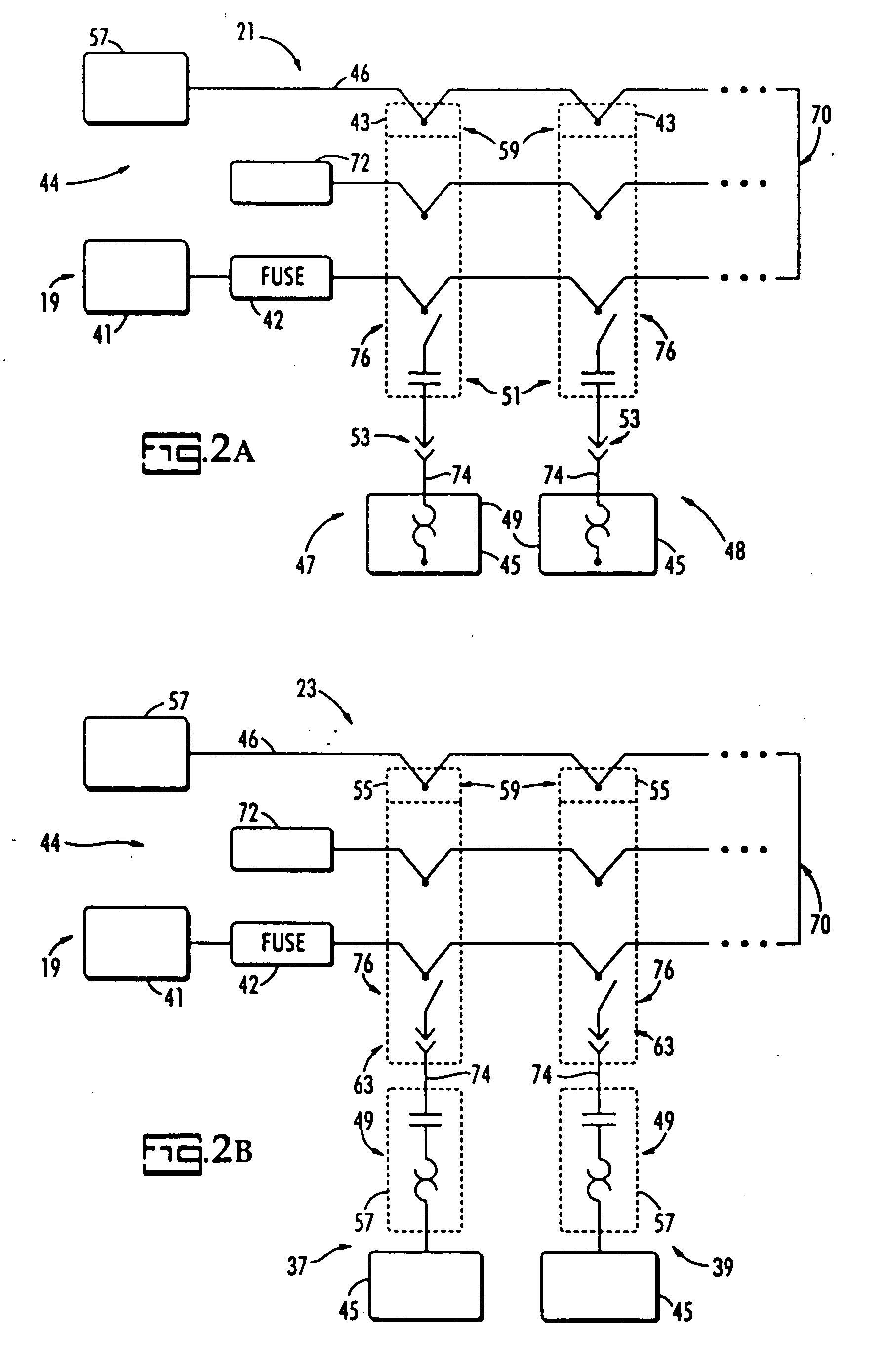
[0018] These and other objects of the invention are also accomplished by providing a decentralized control system for group drive installation. The control system includes an input branch having a field bus and a power input branch having a branch protection device and a control power input, a first drive installation connected with the input branch, at least one subsequent drive installation connected in parallel with the first drive installation from a load side of the branch protection device of the input branch, and an interconnecting line connecting the input branch and the drive installations. Each of the drive installations includes a field distributor and a motor connected to the field distributor via a hybrid cable. By connecting additional drive installations via the interconnecting line with the input branch, the amount of cabling and component expense is reduced in comparison with conventional group motor installations.

Problems solved by technology

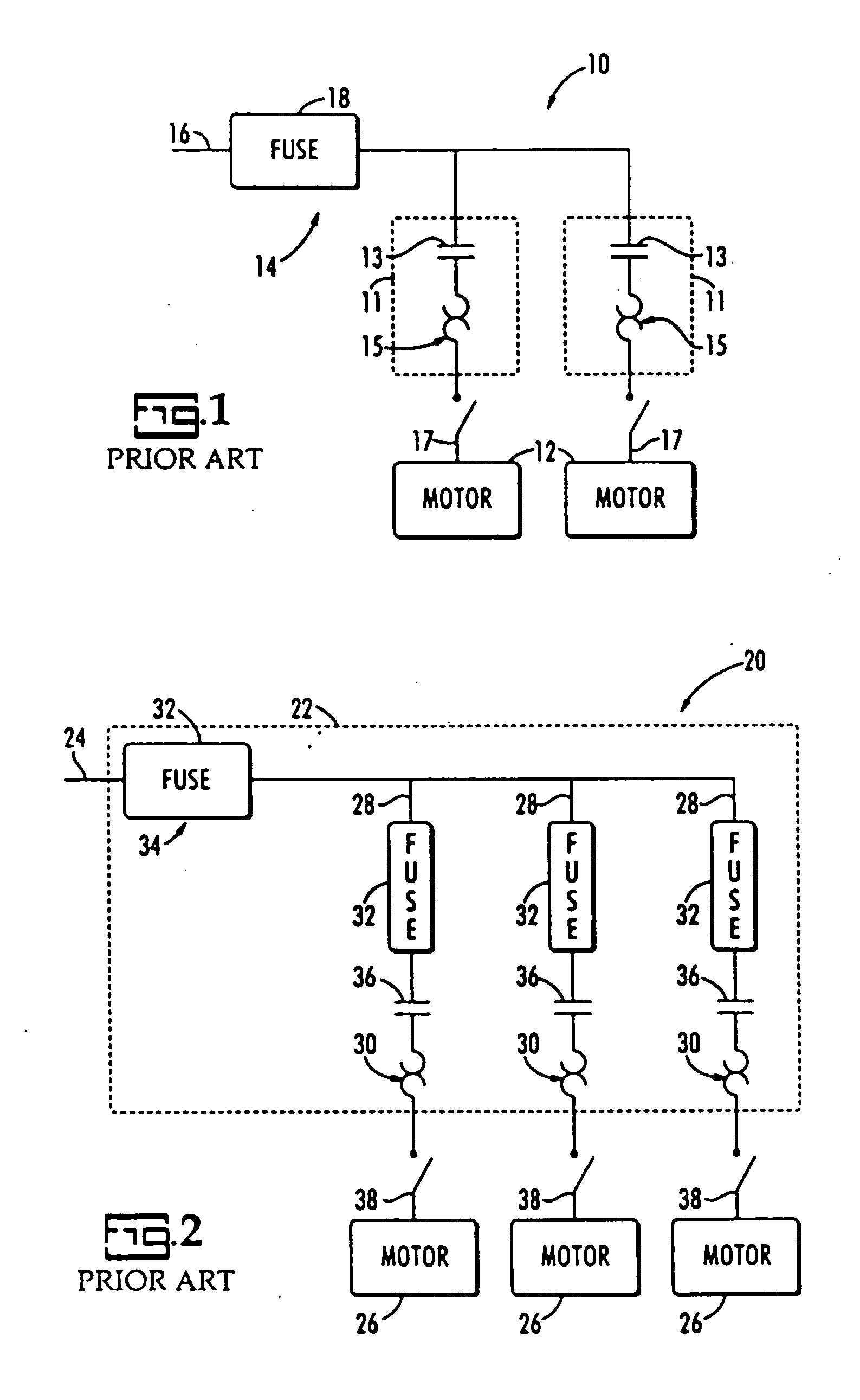
Current group drive installations are limited in size due to the limited number of drives that may be connected to the single input before the main control cabinet size becomes too large and too expensive to implement.
Additionally, each drive branch generally incurs a cabling and component expense that is required in order to satisfy electrical standards or codes.
For example each drive branch that is installed requires individual overload protection, a motor controller, and a motor branch-circuit short-circuit and ground-fault protective device, each of which have an associated cost.
From a practical standpoint, the addition of branches to the main control cabinet generally increases field wiring as well as cabling expense.
In the past, compliance with NEC Article 430.53 of single branch circuit designs for group VFD controlled motor installations has not been accomplished.

Method used


Image

  • Decentralized control of motors
  • Decentralized control of motors
  • Decentralized control of motors

Examples


example 1

[0044]FIG. 3 is a perspective schematic view of an application of the decentralized control system in accordance with one embodiment of the present invention. Cement bags 50 are transported from one location to another by a conveyor, shown generally at 52, having eight conveyor belts 54 successively placed in a row. Each of the conveyor belts 54 has a power demand of about 0.75 kW and is desired to have a variable speed of from 50% to 100%. A sensor 56 is attached to each conveyor belt 54 to detect when a new cement bag arrives on each conveyor belt. It is desirable that each of the conveyor belts 54 is disconnectable from power supply for maintenance of the conveyor 52.

[0045] The equipment description for the conveyor 52 shows a power demand of 0.75 kW and a required speed setting range of 1:2. Eight geared motors 58, such as a MOVIMOT geared motor model type MM07 manufactured by SEW Eurodrive Company with a setting range of 1:5, are each used to drive a conveyor belt 54. For cont...

example 2

[0046]FIG. 4 is a perspective schematic view of an application of the decentralized control system in accordance with a second embodiment of the present invention. In a conveyor, shown generally at 70, used for transporting automobile tires 72, fifteen roller conveyors 74 are each successively placed in a row. Each of the roller conveyors 74 has a power consumption of 0.55 kW, and the speed of the conveyor is desired to be between 33% and 100% via InterBus. A first sensor 76 is located at the front of each roller conveyor 74 to detect the transfer of a tire 72 from the previous roller conveyor. A second sensor 78 is located at the end of each roller conveyor 74 to detect the transfer of the tire to the following roller conveyor. Each roller conveyor 74 is powered only if a tire 72 is located on the conveyor 70. A control light 80 located directly at each roller conveyor 74 indicates the activation of the roller conveyor 74. For maintenance work, the roller conveyors must individuall...

example 3

[0049]FIG. 5 is a perspective schematic view of an application of the decentralized control system in accordance with a second embodiment of the present invention. In a conveyor, shown generally at 90, for transporting automobile tires 92 two roller conveyors 94, 96 used for tire transport are located in a cell together with a robot arm 98, collectively referred to as a robot cell. The robot arm 98 picks up the tires from one of the roller conveyors 96 and mounts each tire 92 onto a wheel rim. Each of the roller conveyors 94, 96 has a power demand of 0.55 kW. Positioning the tires 92 on a roller conveyor 94 is controlled by means of six sensors 100. Brake motors with a speed setting range of 10:1 are to be used for the positioning task. The control in the robot cell is carried out via a DeviceNet interface, which will also be used to control the two roller conveyors 94, 96 of the robot cell. A switch cabinet of the robot cell does not have sufficient space to contain inverters of bo...


PUM


Abstract

A decentralized control system for group drive installation and method of decentralized control of group drives. The decentralized control system has a data and power input branch having a group installation branch protection, a first drive installation connected to the input branch, at least one additional drive installation connected in parallel with the first drive installation at a load side of the group installation branch protection, and a control line interconnecting the input branch, first drive installation, and subsequent drive installations. Each drive installation includes a field distributor and a geared drive connected to said field distributor. The method of decentralized control of drives on a single branch includes selecting a control protocol, providing a power and data input branch having a group installation branch protection, connecting in series with the input branch at least two drive branches, each of the drive branches having a drive with individual overload protection, and transmitting a control signal based on the selected control protocol from the input branch to the drive branches.

Description

FIELD OF THE INVENTION [0001] This invention relates generally to control of multiple motor or drive installations, and more particularly to decentralized control of group motor installations using one branch circuit. BACKGROUND OF THE INVENTION [0002] Electronic motor installations are commonly used in a host of commercial applications including manufacturing systems. For example, a multiple number of motors may be used to drive a series of conveyors at a manufacturing facility. One consideration when developing and implementing group motor installations is compliance with product safety standards and codes. Group motor installations require specific configurations and components, such as fuses and / or overload protection, in order to fulfill National Electrical Code (NEC) requirements established by National Fire Protection Association (NFPA). [0003] As used herein, the term “drive” is defined to mean electronic variable speed motor controller and includes but is not limited to var...

Claims


Application Information

Patent Timeline
IPC IPC(8): H02H5/04H02P5/747
CPCH02P5/747
Inventor MINTZ, RICHARD CALVIN JR.
Owner SEW-EURODRIVE GMBH & CO KG
Learn More