Eureka AIR delivers breakthrough ideas for toughest innovation challenges, trusted by R&D personnel around the world.

Odor control

a technology of odor control and control panel, applied in the direction of water treatment parameter control, biological water/sewage treatment, disinfection, etc., can solve the problems of not solving the problem, not noticing odor, and usually very expensive measures, and achieve the effect of reducing or eliminating odors in wastewater treatment plants

Inactive Publication Date: 2004-09-16
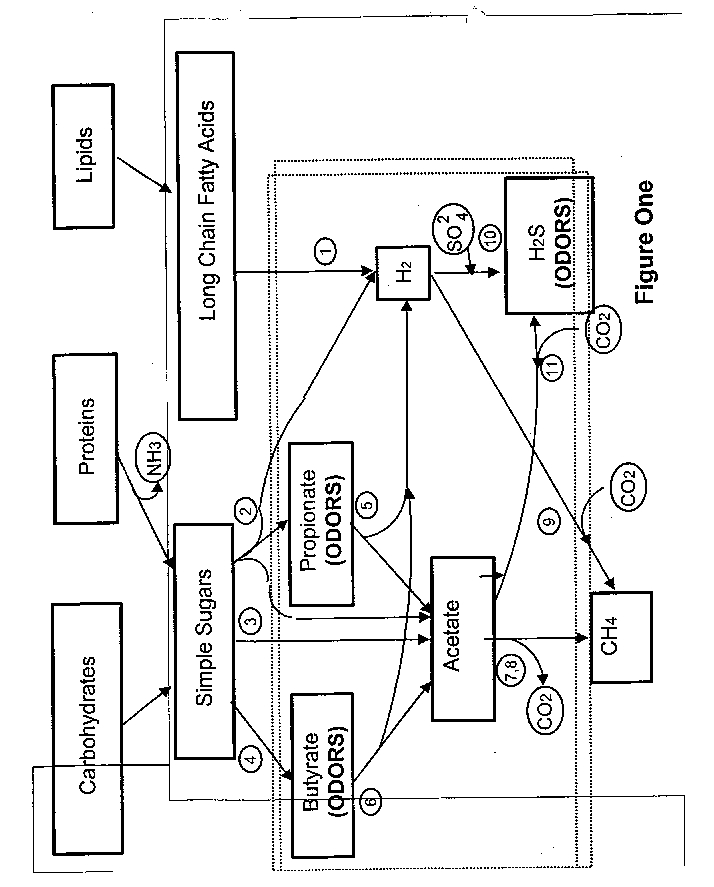
NOVOZYMES AS
View PDF2 Cites 17 Cited by
  • Summary
  • Abstract
  • Description
  • Claims
  • Application Information

AI Technical Summary

Benefits of technology

[0009] It is an object of the invention to reduce or eliminate odors in wastewater treatment plants.
[0015] It is yet another object of the invention to minimize the expense associated with odor treatment in wastewater treatment plants.
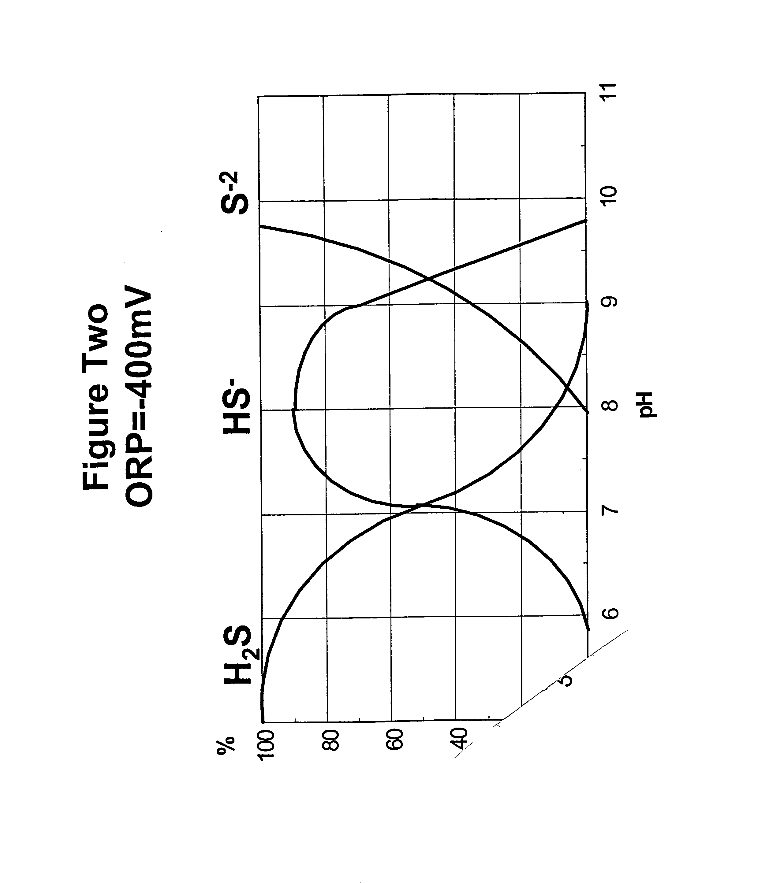
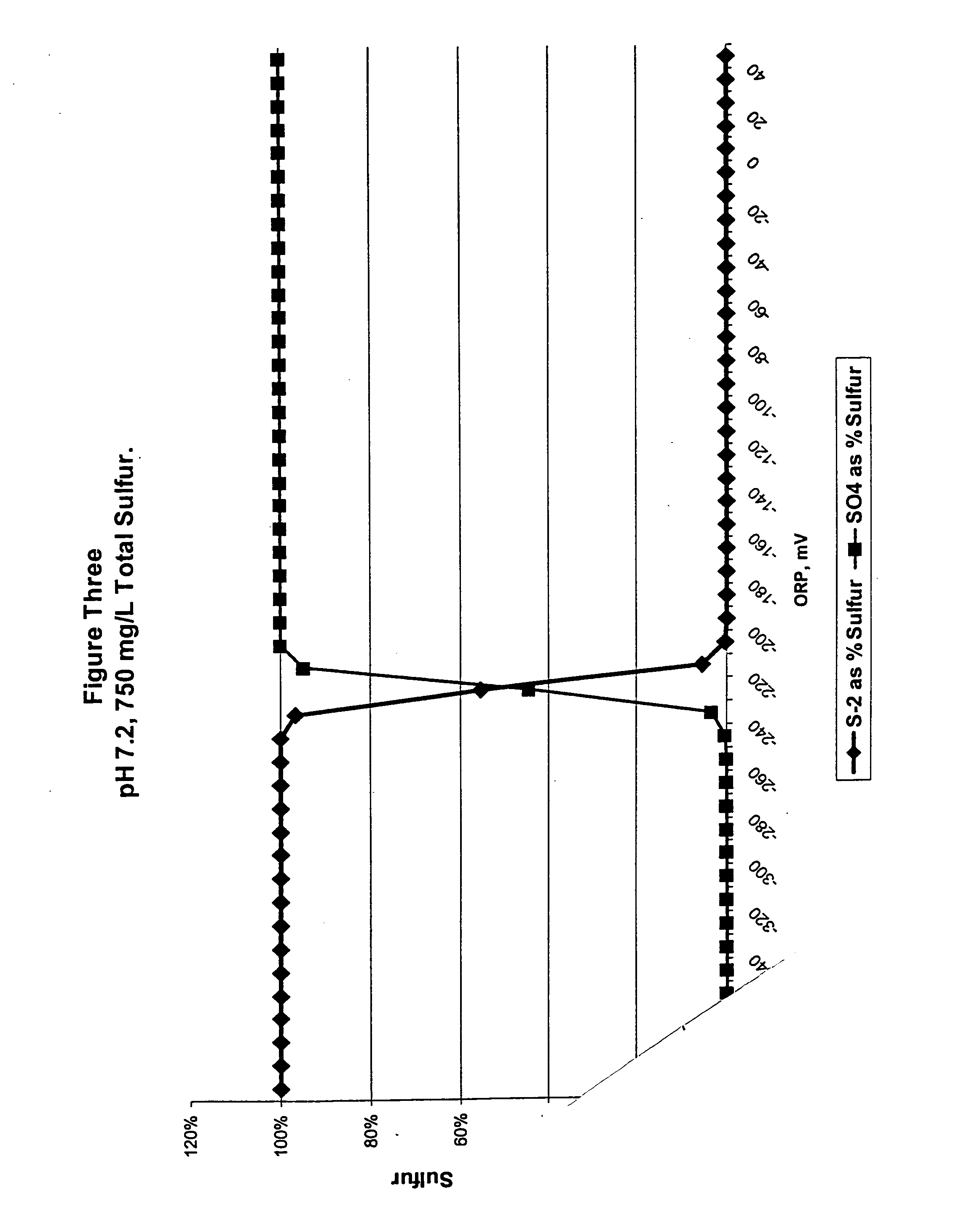
[0039] After pH is fixed, the ORP levels should be increased to a suitable level, although it should be noted that these two steps may be reversed. ORP controls the valence levels of the sulfur molecule which can vary from 2- to 6+. This in turn controls the sulfur speciation in the wastewater. For example, H.sub.2S, which is odor causing, requires sulfur with a valence level of 2-(S.sup.2-). On the other hand, SO.sub.4.sup.2-, which is not odor causing, requires sulfur with a valence level of 6+(S.sup.6+). By changing the ORP in the wastewater, the inventor can alter the species of sulfur present, and thus prevent the formation of odor causing sulfur species.
[0048] Paracoccus denitrificans is capable of aerobic or facultative anaerobic respiration, meaning that it can use O.sub.2 or NO.sub.3.sup.-as an electron acceptor. This provides Paracoccus denitrificans with an advantage over most other sulfur oxidizing bacteria, as well as most sulfur reducing bacteria, because few of either class of bacteria share this trait. When nitrate is added to the system, the Paracoccus denitrificans will use the NO.sub.3.sup.- as an electron acceptor and will use sulfide ions as an electron donor. It will oxidize sulfide, in progressive order, to elemental sulfur SO, thiosulfate S.sub.2O.sub.3.sup.2-, tetrathionate S.sub.4O.sub.6.sup.2-, sulfite SO.sub.3.sup.2- and sulfate SO.sub.4.sup.2- as increasing moles of oxygen are available. None of these oxidized sulfur forms are odor causing. If sufficient electron acceptors are maintained in the wastewater, the Paracoccus denitrificans will become established in the system and predominate over the sulfur reducing bacteria, preventing future odor problems.

Problems solved by technology

These substances most frequently lead to noticeable odors under anaerobic conditions.
Obviously, such measures do not solve the problem, but only cover it up.
These measures are frequently successful, but they can be very expensive, both from the standpoint of capital spent on the equipment itself and in terms of increased operating expense.
Although these methods can be effective, they are usually very expensive.
This expense pressures managers of wastewater facilities to minimize the amount of oxidizers added to the system.
The need to economize can be detrimental if it leads to underdosing.
Underdosing can cause incomplete or partial oxidation, which can create worse odor problems than those the oxidants were introduced to cure.
When chlorine dioxide is added to organic acids, incomplete oxidation can cause the formation of chloroacetic acid, which has a foul odor noticeable at very low concentrations.
These may be effective against sulfide compounds, but do not treat other sources of odors such as organic acids.
Additionally, amines suffer the same disadvantage as all chemical treatments.
Again, these methods are frequently effective, but their results are often short lived.
Typically, the evolution of odors from wastewater treatment lagoons will be due at least in part to the presence of undesirable bacteria in the lagoon.
Unless the conditions that gave rise to the undesirable bacteria are rectified, the newly added bacteria will usually not be able to predominate, and the bacterial population will eventually return to its pre-treatment composition.

Method used


Image

  • Odor control
  • Odor control
  • Odor control

Examples


example ii

[0066] The invention also was tested at pulp and paper mill in Florida during the summer months. The wastewater treatment facility was set up as shown in FIG. 4. The facility consisted of four lagoons. Lagoon A covered 100 acres and contained 325 million gallons. Lagoon B covered 200 acres and contained 225 million gallons. Lagoon C covered 175 acres and contained 185 million gallons. Lagoon D covered 125 acres and contained 130 million gallons. Lagoon A is the only lagoon that was not aerated. Wastewater flowed from the mill to a primary clarifier to lagoon A to lagoon B to lagoon C to lagoon D and then it was discharged. The total retention time in the system was about 30 days. At the time of the test, lagoon A was operating at between about 30.degree. to about 40.degree. C. and historically received BOD.sub.5 loadings of about 45,000 lbs / day.

[0067] Lagoon A was experiencing odor problems which had been unsuccessfully treated with sodium hypochlorite NaOCl and liquid sodium nitrat...


PUM

PropertyMeasurementUnit
oxidation reduction potentialaaaaaaaaaa
Oxidation Reduction Potentialaaaaaaaaaa
oxidation reduction potentialaaaaaaaaaa

Abstract

Disclosed herein is a method for treating odors in wastewater treatment bodies. The pH of the body is preferably established above about 6 and most preferably above about 7, usually by adding a base to the body. The oxidation reduction potential of the body is established at about -300 mV or higher and more preferably about -200 mV or higher, usually by adding an oxidizing agent such as oxygen or nitrates. After these conditions are established, sulfur oxidizing bacteria are added to the body. These preferably include Paracoccus denitrificans (formerly called Thiosphaera pantotropha) ATTC number 35,512. The sulfur oxidizing bacterial population should be established at levels of at least about 1x10<4 >cfu / mL and more preferably at levels of 1x10<5 >to 1x10<6 >cfu / mL or higher. The increased ORP and pH levels make sulfate reduction thermodynamically unfavorable. Additionally, the presence of an alternative electron acceptor such as oxygen or nitrate allows the sulfur oxidizing bacteria to oxidize organic acids.

Description

[0001] 1. Field of the Invention[0002] The invention relates to wastewater treatment in general and to methods of controlling odors during treatment in particular.[0003] 2. Prior Art[0004] Objectionable odors are caused by a variety of substances typically present in wastewater. These include sulfur and several sulfur containing compounds including hydro sulfuric acid, sulfuric acid, mercaptans (R--SH) including especially methyl and dimethyl mercaptans, and dimethyl disulfide (DMDS); numerous organic acids including propionic acid, acetic acid, butyric acid, isovaleric acid; ammonia; urea; and various terpenes including carene, pinene, limonene. These substances most frequently lead to noticeable odors under anaerobic conditions.[0005] There are several approaches to odor problems known in the art. One solution is to add masking agents and perfumes to the wastewater. Obviously, such measures do not solve the problem, but only cover it up. Another solution is to add aerating equipme...

Claims


Application Information

Patent Timeline
Patent Type & Authority Applications(United States)
IPC IPC(8): C02F1/66C02F3/34C12P11/00
CPCC02F1/66C02F3/345Y10S210/916C02F2303/02C12P11/00C02F2209/04
Inventor CHRISTIANSEN, JOHN A.
Owner NOVOZYMES AS
Why Eureka
Eureka Blog
Learn More