

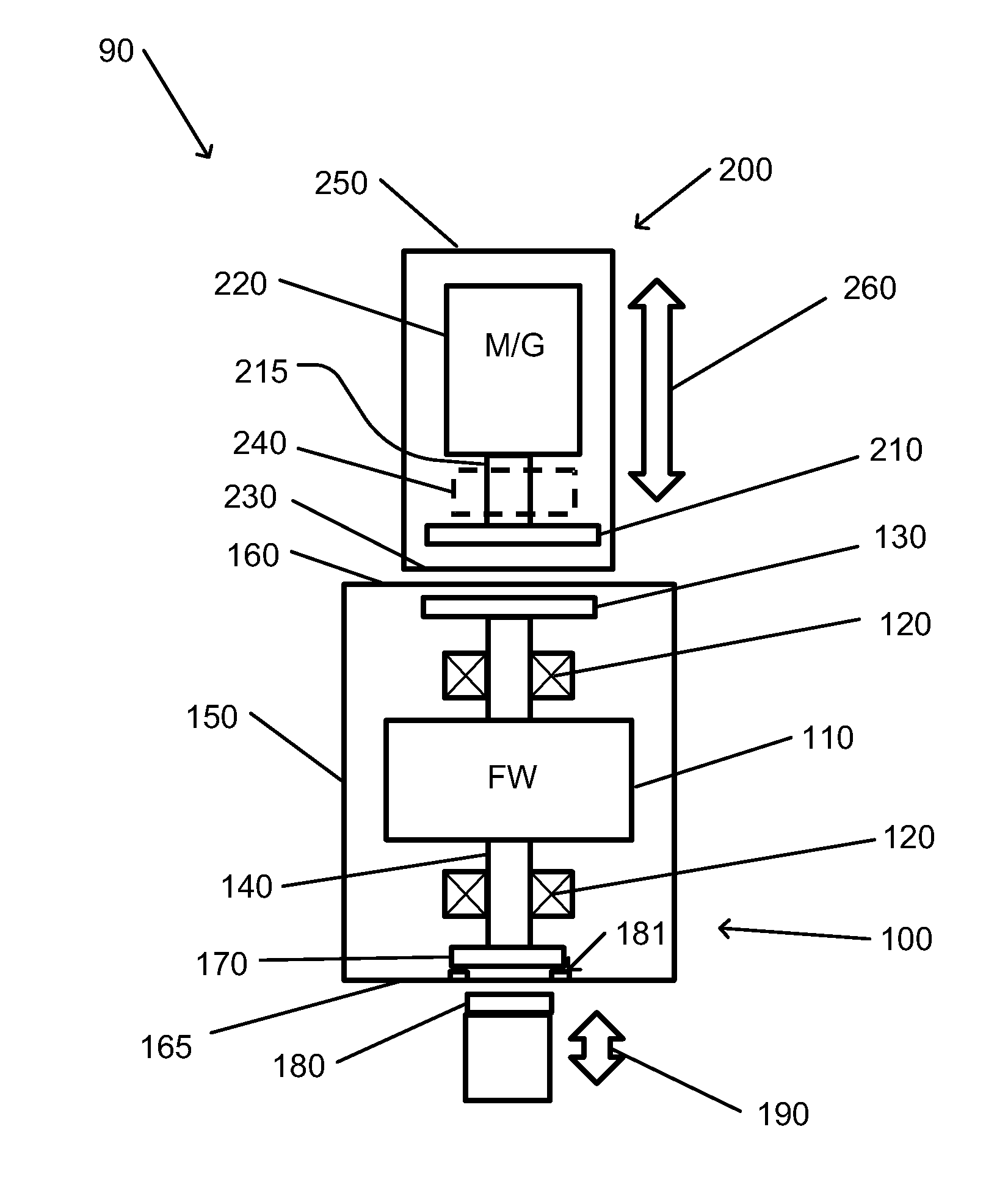
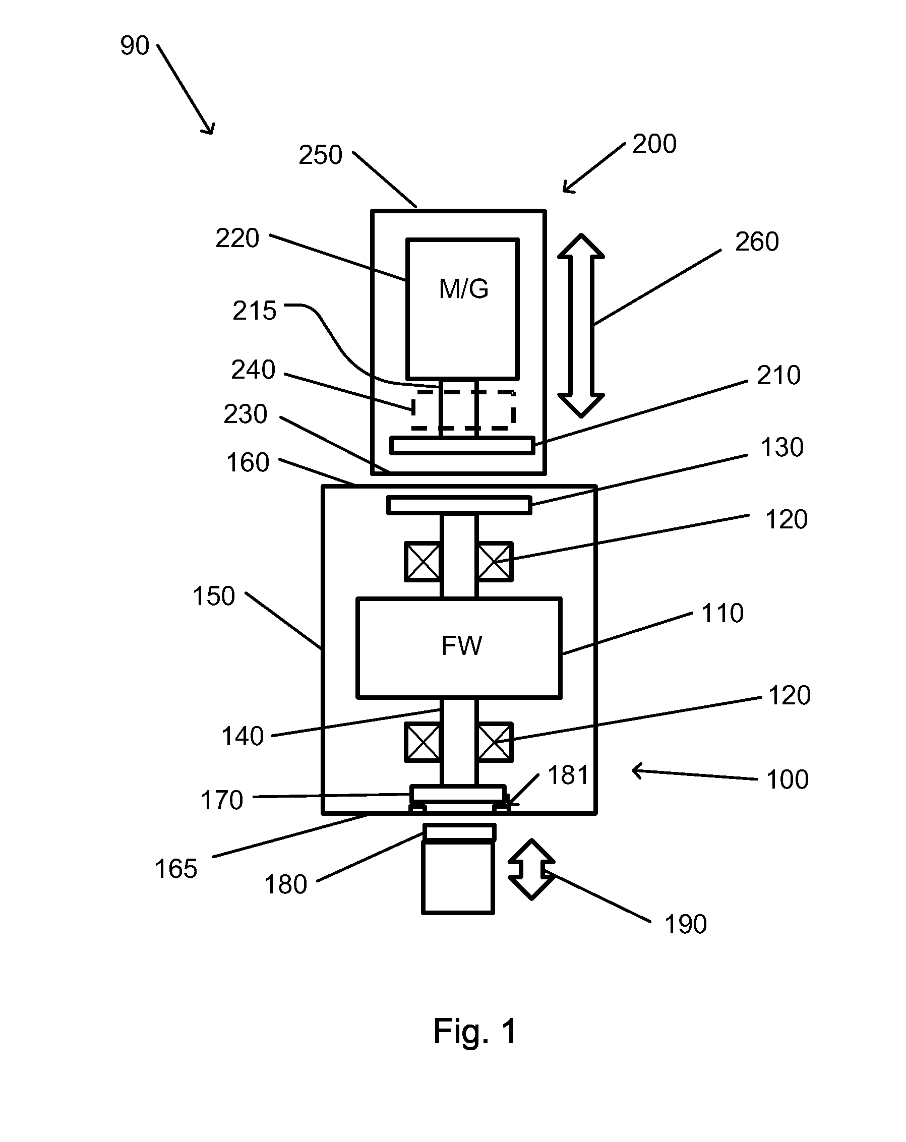
Magnetically coupled flywheel
a magnetic coupling and flywheel technology, applied in the field of flywheels, can solve the problems of loss of stored energy, insensitive flywheel systems to environmental factors, and fluctuation of electrical power from the grid, so as to reduce imbalance forces
- Summary
- Abstract
- Description
- Claims
- Application Information
AI Technical Summary
Benefits of technology
Problems solved by technology
Method used
Image

Examples
Embodiment Construction
[0057]In the following detailed description, numerous specific details are set forth in order to provide a thorough understanding of the invention. However, it will be understood by those of ordinary skill in the art that the invention may be practiced without these specific details. In other instances, well-known methods, procedures, components, modules, units and / or circuits have not been described in detail so as not to obscure the invention.
[0058]Embodiments of the invention may include an article such as a computer or processor readable medium, or a computer or processor storage medium, such as for example a memory, a disk drive, or a USB flash memory, encoding, including or storing instructions, e.g., computer-executable instructions, which when executed by a processor or controller, carry out methods disclosed herein.
[0059]In accordance with embodiments of the present invention, a flywheel energy storage system includes a flywheel. The flywheel, as well as any shaft, axle, or...
PUM
 Abstract
Description
Claims
Application Information