Printing apparatus

a printing apparatus and printing technology, applied in the direction of digital output to print units, instruments, transportation and packaging, etc., can solve the problems of increasing the number of sensors needed, the user's difficulty in taking out the first tray,

Active Publication Date: 2015-06-18
SEIKO EPSON CORP
View PDF2 Cites 3 Cited by
  • Summary
  • Abstract
  • Description
  • Claims
  • Application Information

AI Technical Summary

Benefits of technology

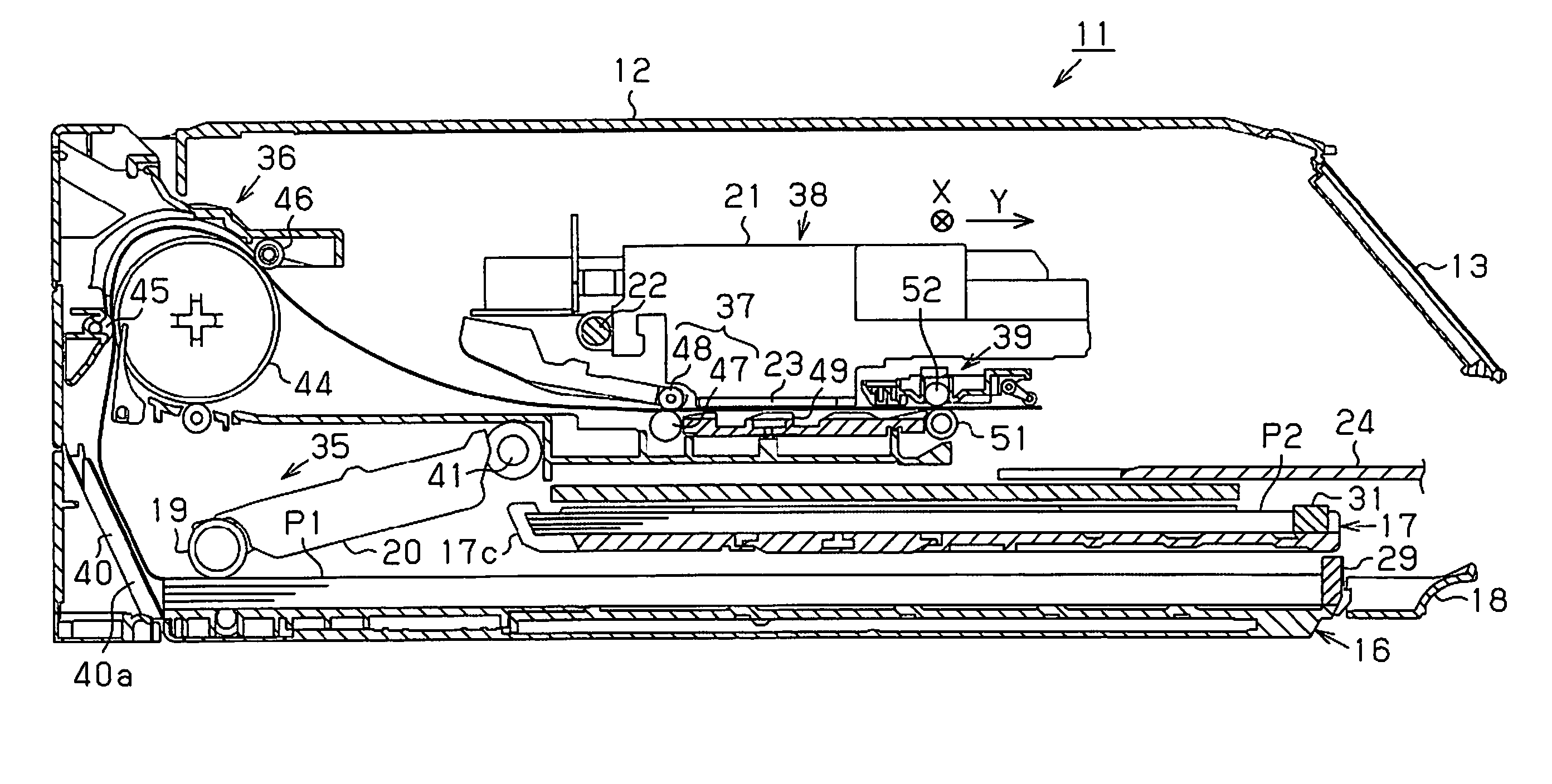
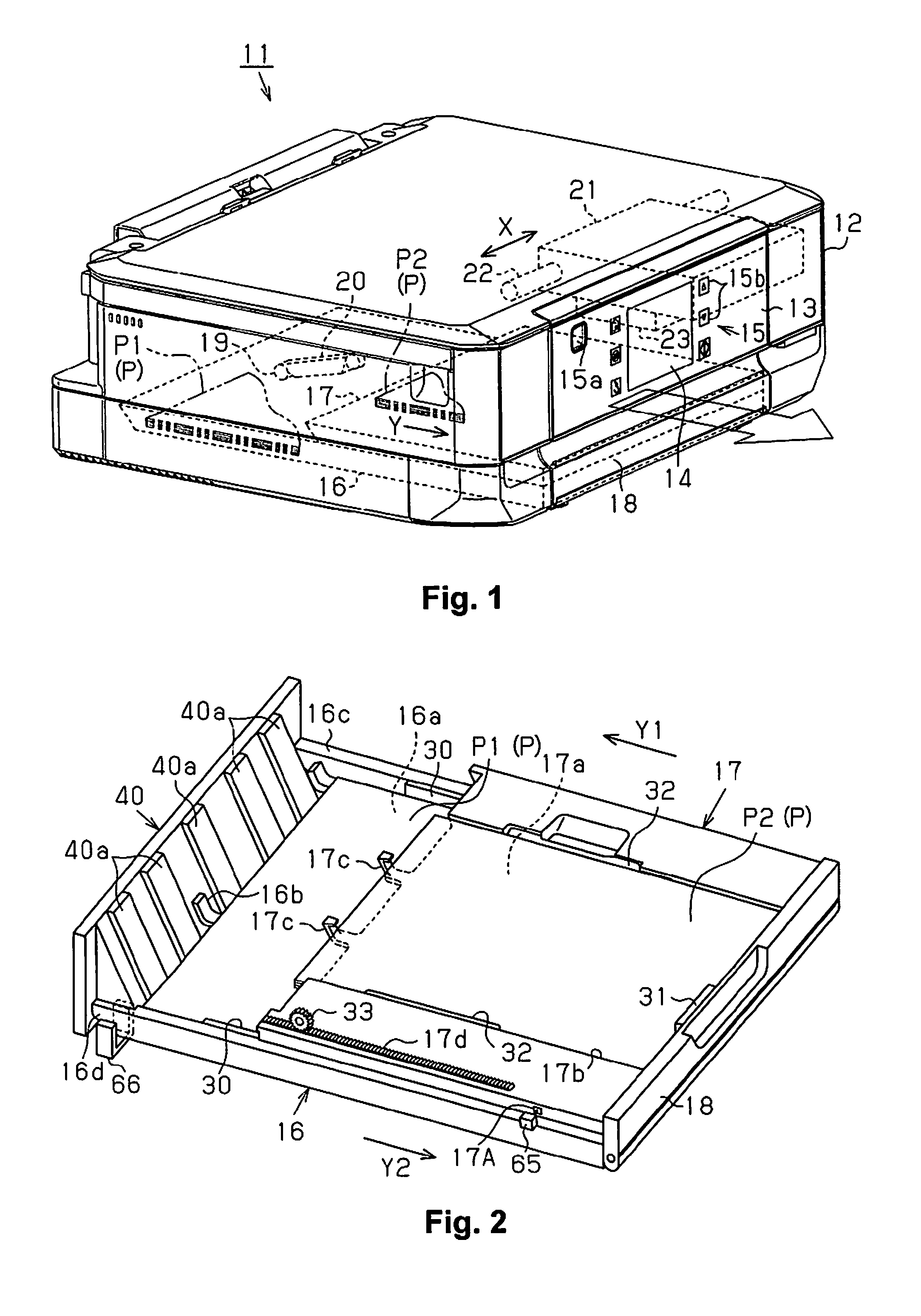
[0009]The present invention is carried out in order to solve these problems and has an object of providing a printing apparatus where it is possible to detect a plurality of position states for a movable medium accommodating section which are necessary in controlling the printing apparatus even using sensors which are fewer in number than the number of position states which are targets for detection.
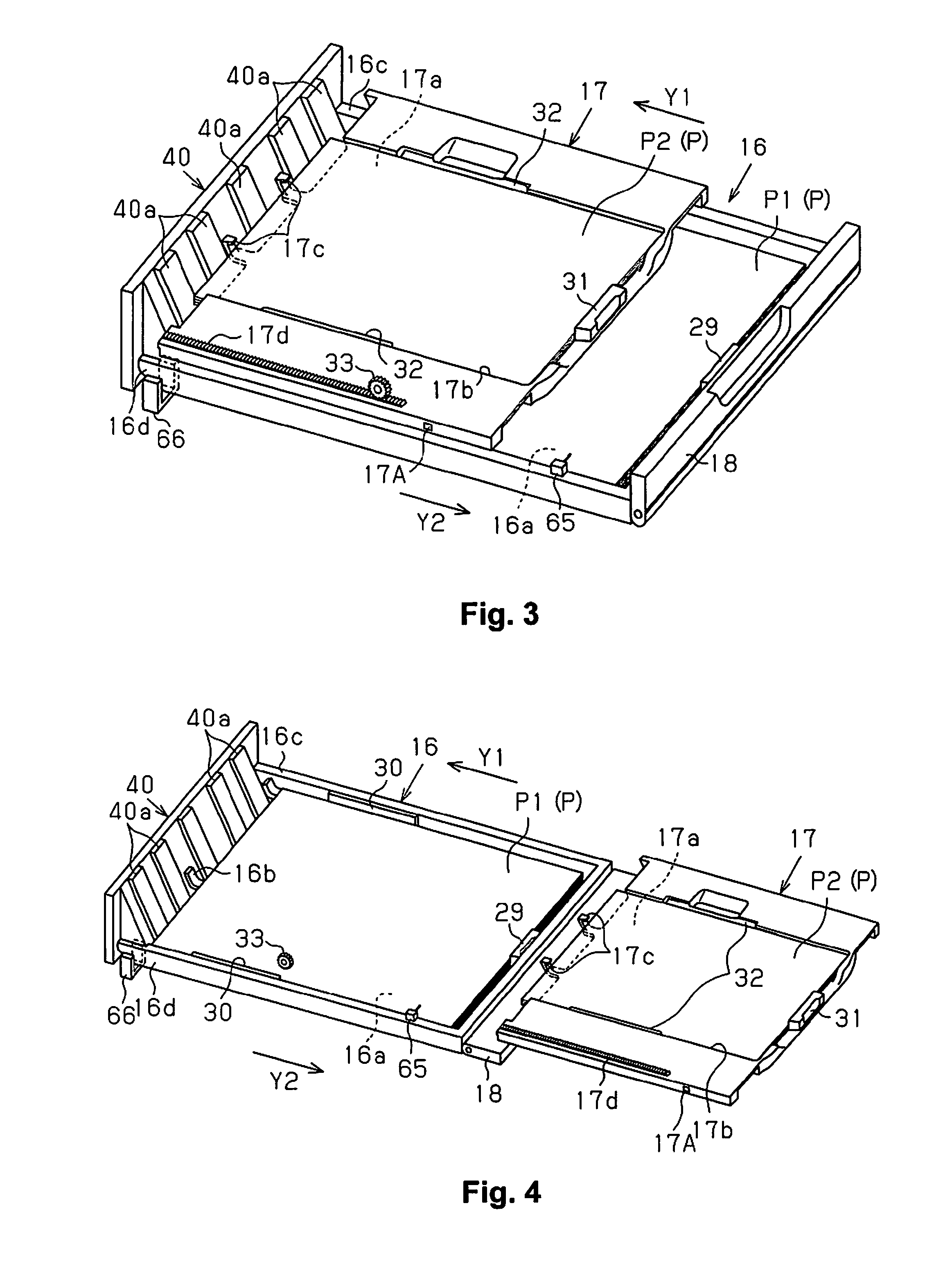
[0012]According to this configuration, the setting position is detected by the sensor identifying the section to be identified of the medium accommodating section and the medium accommodating section reaching the supplying position is detected when the medium accommodating section hits the regulating section and the drive load on the driving section exceeds a threshold. As such, it is possible to detect a plurality of the position states for the movable medium accommodating section which are necessary in controlling the printing apparatus even using sensors which are fewer in number than the plurality of position states which include the setting position and the supplying position of the movable medium accommodating section. For this reason, it is possible to suppress the number of parts in the printing apparatus as much as possible.
[0016]According to this configuration, there are cases, although rare, where a user pushes in the medium accommodating section deep into the body of the printing apparatus as a case where the sensor switches from the identifying state to the non-identifying state other than when taking out the medium accommodating section when the driving section is not driving the medium accommodating section. In this case, the sensor is in the identifying state after driving for a predetermined driving amount when the driving section is driven so that the medium accommodating section is to be moved to the setting position after the sensor switches from the identifying state to the non-identifying state. In contrast to this, the sensor is not in the identifying state even after driving with a predetermined driving amount in a case where the medium accommodating section is taken out. For this reason, taking out of the medium accommodating section is detected when the sensor is not in the identifying state even after driving with a predetermined driving amount. As such, it is possible to correctly detect taking out of the medium accommodating section without mistakes in cases where the medium accommodating section is pushed in.
[0018]According to this configuration, it is not possible to distinguish mounting of the medium accommodating section or pulling back from the supply position side only by the result of identifying by the sensor since the sensor switches from the non-identifying state to the identifying state also in a case where a user pulls back the medium accommodating section, which is pushed toward the supply position side, to the setting position if there is a configuration where, for example, there is only one of the sections to be identified for identifying the setting position. However, it is possible for a user to more correctly detect mounting of the medium accommodating section by differentiating mounting and pulling back of the medium accommodating section using the number of identifications by the sensors since the number of the second sections to be identified which are provided at positions more to the insertion direction side than the first section to be identified of the medium accommodating section is more than the number of the second sections to be identified which are provided at positions on the taking out direction side.
[0020]According to this configuration, it is not possible to distinguish taking out of the medium accommodating section or pushing in to the supplying position side only by the result of identifying by the sensor since the sensor switches from the identifying state to the non-identifying state also in a case where a user pushes in the medium accommodating section from the setting position toward the supplying position side if there is a configuration where, for example, there is only one of the sections to be identified for identifying the setting position. However, it is possible for a user to more correctly detect taking out of the medium accommodating section by differentiating taking out and pushing in of the medium accommodating section using the number of identifications of the second sections to be identified by the sensors since the number of the second sections to be identified which are provided at positions more to the insertion direction side than the first section to be identified of the medium accommodating section is more than the number of the second sections to be identified which are provided at positions on the taking out direction side.
[0022]According to this configuration, it is possible for the control section to detect mounting of the second medium accommodating section by the second sensor identifying the end portion of the second medium accommodating section when the user mounts the second medium accommodating section into the apparatus body. In addition, it is not necessary to separately provide a member to be identified since the target for detection for the second sensor is the end portion of the second medium accommodating section on the downstream side of the insertion direction into the body of the printing apparatus.

Problems solved by technology

In this type of apparatus, it is difficult for a user to take out the first tray when the first tray which is movable is at the paper supplying position which is at a far side in an apparatus body.
Furthermore, there is a problem in that the number of sensors which are necessary increase if the position states which are targets for detection increase such as in a case where it is necessary to detect mounting of the supply tray or in a case where it is necessary to detect taking out of the supply tray as in Japanese Unexamined Patent Application Publication No. 2002-278377.

Method used


Image

  • Printing apparatus
  • Printing apparatus
  • Printing apparatus

Examples


second embodiment

[0144]A second embodiment will be described next with reference to the diagrams. It is not possible for movement direction to be detected when the movable tray 17 is being inserted and extracted in the first embodiment, but it is possible for movement direction to also be detected when the movable tray 17 is being inserted and extracted in the second embodiment. Here, the configuration for detecting the position of the movable tray 17 and the content for controlling which is performed in order to detect the position of the movable tray 17 are different to the first embodiment but, since the other configurations are the same as the first embodiment, the configurations which are shared with the first embodiment are given the same reference numerals and the description thereof is omitted.

[0145]As shown in FIG. 13, in addition to the section to be identified 17A, a section to be identified 17B with a platform shape in a planar view is formed at the side section of the movable tray 17 in...


PUM


Abstract

A printer includes a first sensor configured to identify a section to be identified of a movable tray. A computer in the printer drives a motor in a direction where the movable tray heads to a supplying position and stops driving the motor when an impact, where the drive load on the motor exceeds a threshold due to the movable tray hitting a separating mechanism which is at the supplying position, is detected. In addition, the computer drives the motor in a direction where the movable tray heads to a setting position, and stops driving the motor and arranges the movable tray at the setting position when the first sensor is on due to the section to be identified being identified.

Description

CROSS-REFERENCE TO RELATED APPLICATIONS[0001]This application claims priority to Japanese Patent Application No. 2013-258528 filed on Dec. 13, 2013. The entire disclosure of Japanese Patent Application No. 2013-258528 is hereby incorporated herein by reference.BACKGROUND[0002]1. Technical Field[0003]The present invention relates to a printing apparatus which is provided with a movable tray which accommodates a medium such as paper sheets.[0004]2. Related Art[0005]A system, where a supply tray (a medium accommodating section) with upper and lower levels which supplies paper sheets is provided independently so as attaching and detaching is possible, is disclosed in, for example, Japanese Unexamined Patent Application Publication No. 2005-330105 as this type of printing apparatus. A first tray (a first medium accommodating section) on an upper level is a movable tray, the length of the first tray in a medium feeding direction is shorter than a second tray (a second medium accommodating...

Claims


Application Information

Patent Timeline
Patent Type & Authority Applications(United States)
IPC IPC(8): B65H7/20B65H7/02G06K15/00B65H1/14
CPCB65H7/20B65H1/14G06K15/4065G06K15/005B65H7/02B65H1/04B65H2405/324B65H2407/21B65H2511/20B65H2515/70B65H2220/03B65H2220/01
Inventor SHIRANE, TATSUYAMIYAKE, TOSHIO
Owner SEIKO EPSON CORP
Why Eureka
Try Eureka