
Pump and fuel injection device

a fuel injection device and pump technology, applied in the direction of piston pumps, positive displacement liquid engines, charge feed systems, etc., can solve the problems of high cost, high cost of fuel injection devices using such pumps, and high cost, and achieve low cost, resource saving, and suppress the effect of parts

Inactive Publication Date: 2017-08-24
MIKUNI CORP
View PDF4 Cites 0 Cited by
  • Summary
  • Abstract
  • Description
  • Claims
  • Application Information

AI Technical Summary

Benefits of technology

The patent text is discussing the high costs of conventional pumps and fuel injection devices. These costs are due to the need for motors to operate the pumps and the need for batteries to power the motors. The technical effect of the patent is to provide a more cost-effective solution for pumps and fuel injection devices.

Problems solved by technology

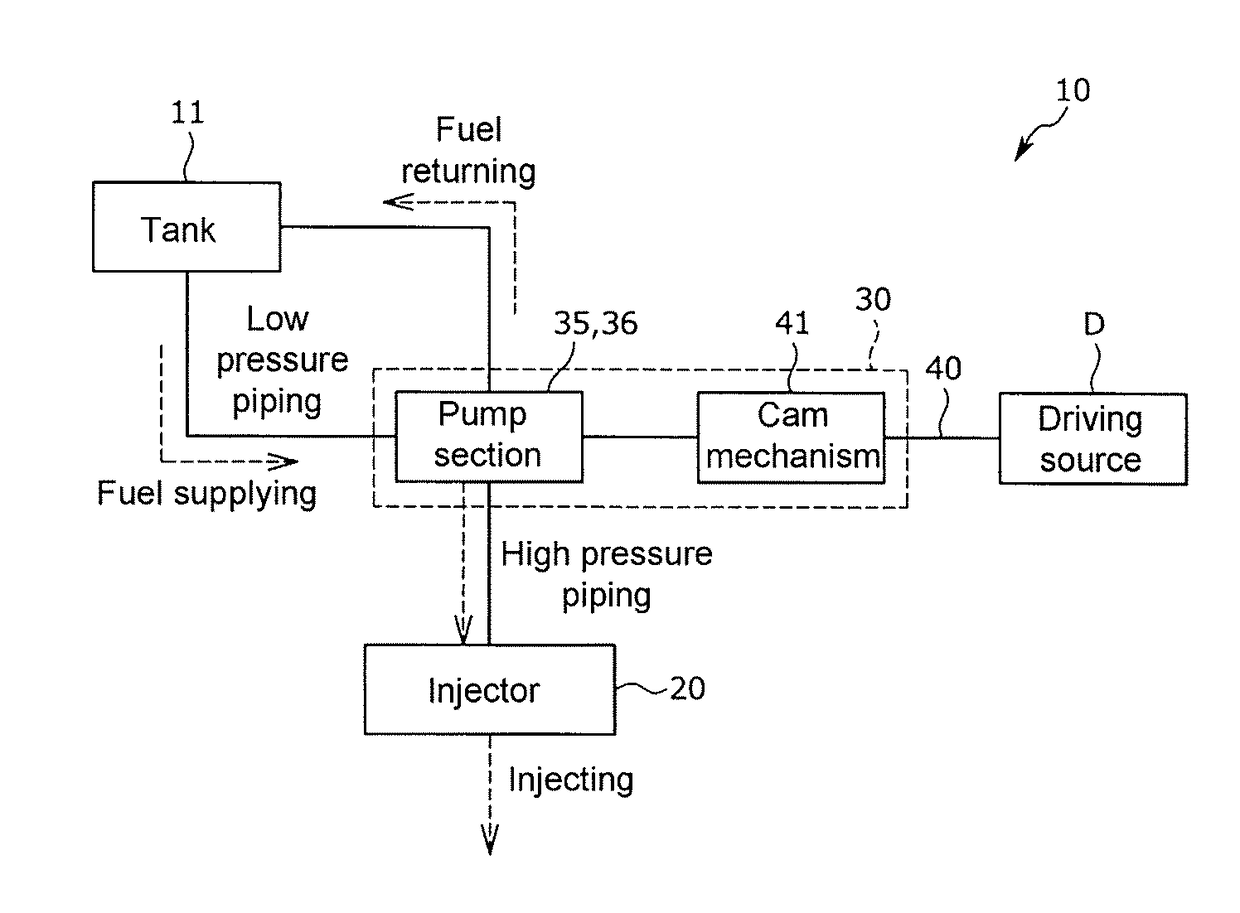
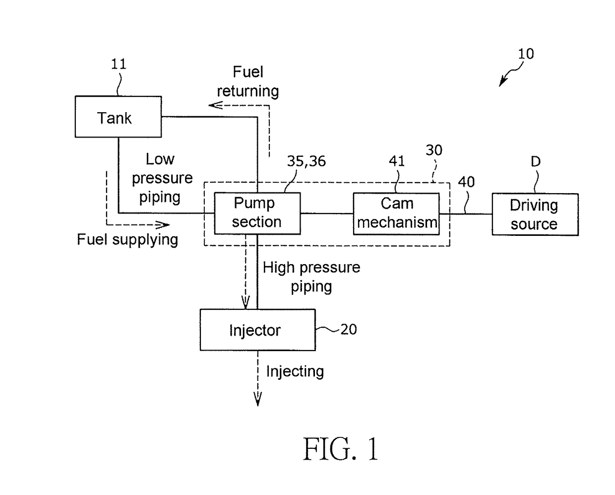
The conventional pump as recited in Patent Document 1 is high in costs due to the motors required for operating the pump.
Other than that, a fuel injection device using such pump is also high in costs due to batteries required for operating the motors.
When a fuel injection (FL, an electronically controlled fuel injection) system for achieving low fuel efficiency, low exhaust and higher starting rate is applied to those models operated without power generating devices or batteries, the costs will be considerably high since a new power generating device for operating the FI system must be installed.
In this case, if vapor is sucked in by the pump, fuel discharge failure and fuel pressure failure will occur to make maintaining a stable operation even harder.
Also, when restarting the engine, it is difficult for the engine to start if vapor is sucked in by the pump.

Method used


Image

  • Pump and fuel injection device
  • Pump and fuel injection device
  • Pump and fuel injection device

Examples


modification example

OF BEARING STRUCTURE

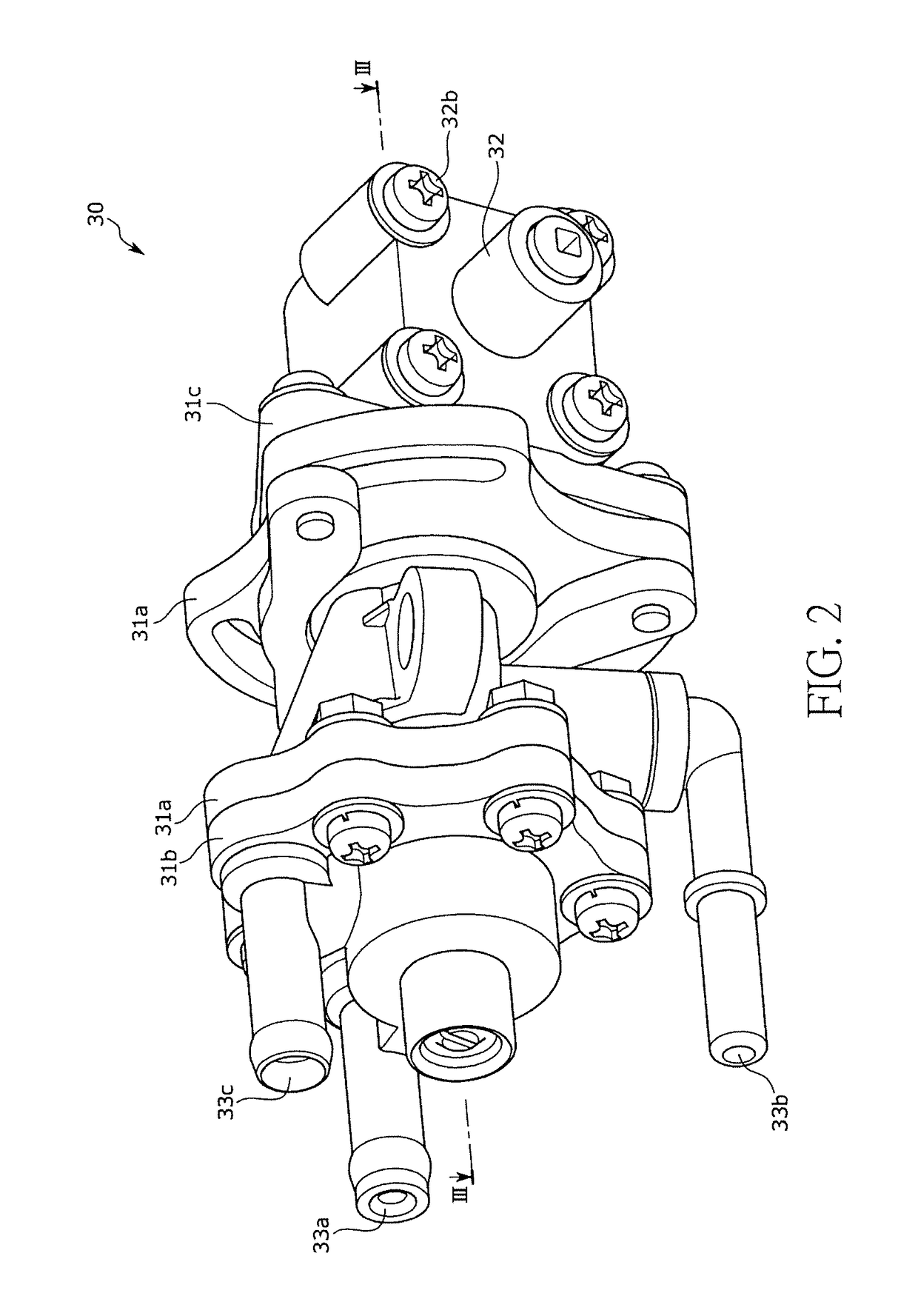
[0129]In the configuration for operating the pump 30 by using the rotary cable 40 to retrieve the rotational torque from the crank shaft 61, the lateral vibration of the joint member 38 connected to the inner cable 40a may occur. Under such circumstance, it is concerned that the timing for feeding the fuel to the injector 20 may not be the ideal timing since it is difficult for the eccentric cam 41a fitted to the joint member 38 to rotate smoothly.

[0130]To prevent such adverse condition, the modification examples regarding the bearing structure for preventing the lateral vibration of the joint member 38 are described below with reference to FIG. 13 to FIG. 15.

[0131]Herein, FIG. 13 is a partial enlarged cross-sectional view illustrating a configuration of the pump 30 using a bearing 70 to support the joint member 38. FIG. 14 is a partial enlarged cross-sectional view illustrating a configuration of the pump 30 using a cylindrical bush 71a to support the joint memb...


PUM


Abstract

Provided are a pump and a fuel injection device, in which fuel discharge failure and fuel pressure failure are prevented by suppressing generation of vapor, thereby enabling vehicles, agricultural machines, generators, and the like, which are provided with internal combustion engines, to operate stably. A pump is provided with: a pump body having a pump chamber defined therein; a plunger reciprocating in response to the rotation of an eccentric cam, thereby feeding fuel sucked in the pump chamber to an injector; and an input portion to which rotational torque from the outside is applied. The input portion is provided with the eccentric earn coupled to a joint member connected to a rotating member; a boss section for rotatably supporting the joint member; and a bush for restricting the axial movement of the joint member.

Description

BACKGROUND OF THE INVENTION[0001]Field of the Invention[0002]The invention relates to a pump and a fuel injection device, and more particularly, to a pump and a fuel injection device for enabling internal combustion engines used in vehicles, agricultural devices, power generators and the like, to stably operate.[0003]Description of Related Art[0004]With regard to an internal combustion engine such as a motorcycle engine, the internal combustion engine is commonly used to pump a fuel from a tank to an injector by a pump, inject the fuel by the injector, and then pressurize a gas mixed by the fuel and air in a cylinder through a piston to cause an explosion so as to generate power.[0005]In Patent Document 1, a pump includes a plunger pump section and a diaphragm pump section and is operated by utilizing a rotational torque from each of separated disposed motors.[0006]In detail, the rotational torque of an output shaft of the motor is transmitted to a cam rotatably installed on a cylin...

Claims


Application Information

Patent Timeline
Patent Type & Authority Applications(United States)
IPC IPC(8): F02M37/06F04B17/05F04B9/04
CPCF02M37/06F04B17/05F04B9/04F04B9/042F04B23/06F04B43/02
Inventor MIZUI, HIROSHIMURAKAMI, HIROKAZU
Owner MIKUNI CORP
Learn More