Propeller shaft
a technology of propeller shaft and shaft shaft, which is applied in the direction of engine seals, yielding couplings, couplings, etc., can solve the problems of increasing installation time and manufacturing costs, and achieve the effect of suppressing the impact absorption potential
- Summary
- Abstract
- Description
- Claims
- Application Information
AI Technical Summary
Benefits of technology
Problems solved by technology
Method used
Image
Examples
first embodiment
Operation of First Embodiment
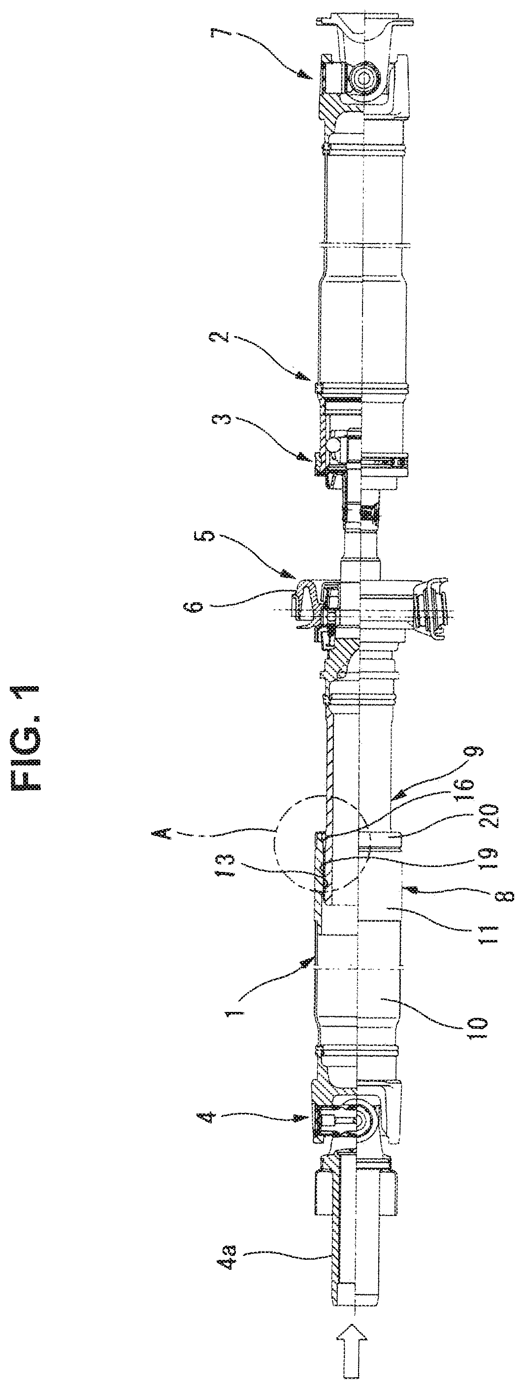
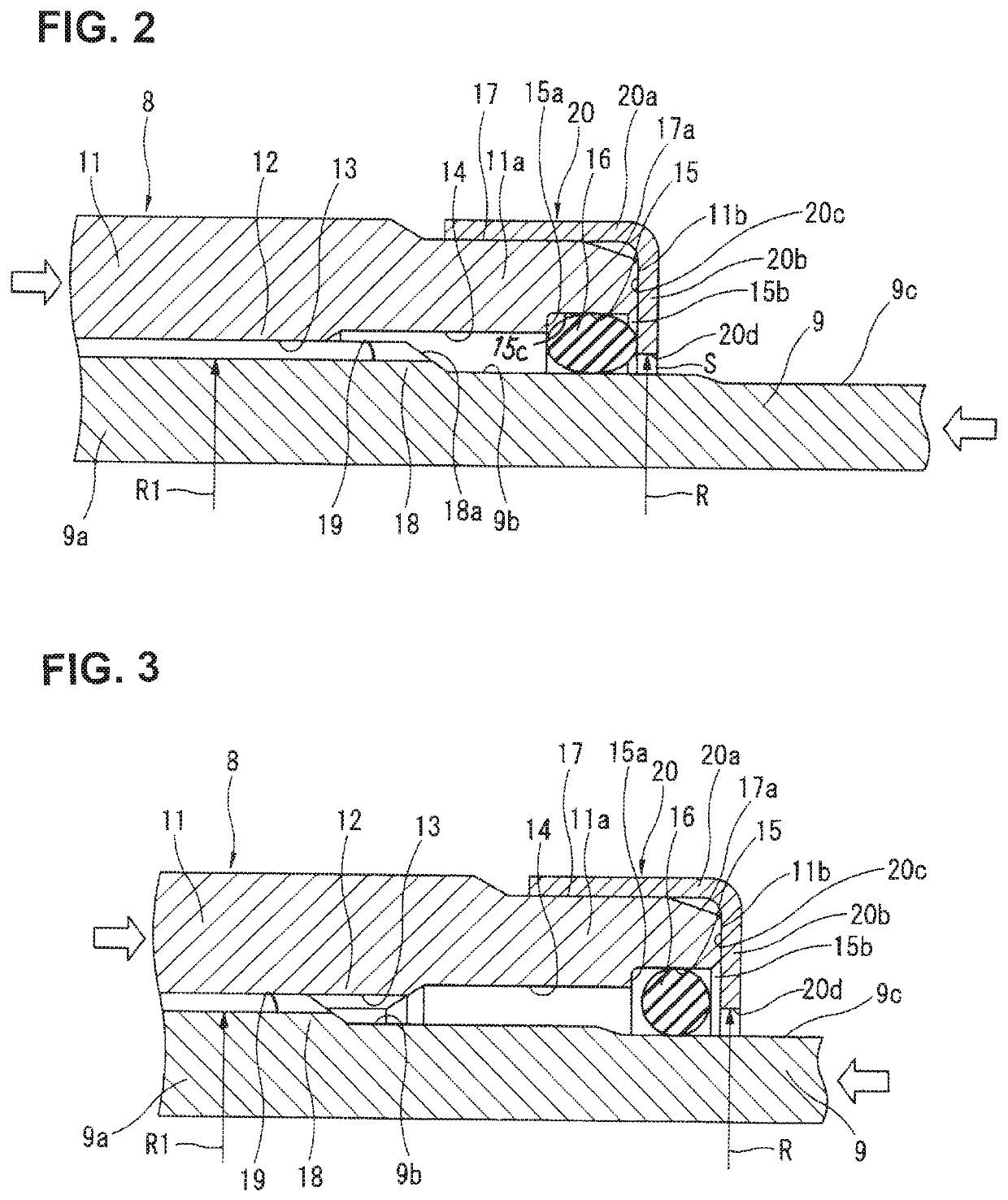
[0045]With the previously-discussed arrangement, the power transmission shaft of the first embodiment operates as follows:
[0046]For instance, during a vehicle collision, when an excessive input load is applied from the side of the transfer through the first cruciform joint 4 to the front-side shaft 8 of the shaft 1 (see the left-hand side voided arrow of FIG. 2), a large force is exerted on the second tube 11 of the front-side shaft 8 in an axially rearward direction such that the second tube 11 is axially displaced toward the rear-side shaft 9 via the spline joint (i.e., female spline joint portion 13 and male spline joint portion 19 spline-connected each other). Also, during a vehicle collision, when an excessive input load is applied from the side of the rear differential through the second cruciform joint 7 to the rear-side shaft 9 of the shaft 1 (see the right-hand side voided arrow of FIG. 2), a large force is exerted on the rear-side shaft 9 in an...
second embodiment
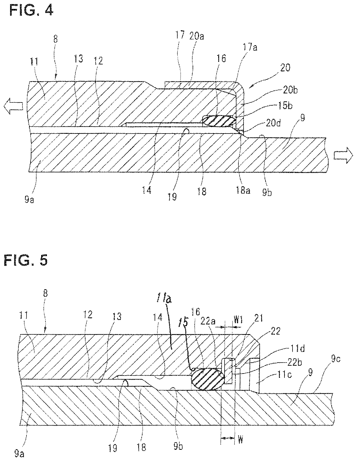
[0065]Referring to FIG. 5, there is shown the power transmission shaft (the vehicle propeller shaft) of the second embodiment. Seal housing groove 15 is formed in the distal part of the cylindrical inner peripheral surface 14 at an axial position somewhat spaced apart from the rearmost end face of the rear end 11a of the second tube 11. Additionally, a diametrically-enlarged retainer housing annularly recessed groove (simply, retainer housing groove) 21 is formed axially outside of the seal housing groove 15, such that these grooves 15 and 21 are juxtaposed to each other. A diametrically-expanding / contracting, elastically deformable snap-action retainer member 22 is held in the retainer housing groove 21.
[0066]The rear-half inner peripheral surface (the right-hand side inner peripheral surface, viewing FIG. 5) of the opening 11c of the rear end 11a of the second tube 11 is configured as an annular surface having a uniform inside diameter. On the other hand, the front-half inner peri...
third embodiment
[0074]Referring to FIG. 6, there is shown the power transmission shaft (the vehicle propeller shaft) of the third embodiment. A seal member 24 and a retainer member 23 are united with each other. That is, seal member 24 and retainer member 23 are formed integral with each other and configured as a so-called oil-seal structure.
[0075]That is, seal housing groove 15 is formed in the cylindrical inner peripheral surface of the rearmost end portion of the rear end 11a of the second tube 11 and configured as an annular surface having a uniform inside diameter.
[0076]As shown in FIG. 6, retainer member 23 is formed and bent into a substantially C-shape in cross-section. Retainer member 23 is comprised of an outer cylinder part 23a press-fitted into the inner peripheral surface of seal housing groove 15 and a retainer part 23b bent to extend in the direction perpendicular to the axial direction of the second tube 11. The outside diameter of outer cylinder part 23a is dimensioned to be slight...
PUM
 Abstract
Description
Claims
Application Information
 - R&D
- Intellectual Property
- Life Sciences
- Materials
- Tech Scout
- Unparalleled Data Quality
- Higher Quality Content
- 60% Fewer Hallucinations
Browse by: Latest US Patents, China's latest patents, Technical Efficacy Thesaurus, Application Domain, Technology Topic, Popular Technical Reports.
© 2025 PatSnap. All rights reserved.Legal|Privacy policy|Modern Slavery Act Transparency Statement|Sitemap|About US| Contact US: help@patsnap.com


