Damping bearing

Active Publication Date: 2015-06-25
SIEMENS ENERGY GLOBAL GMBH & CO KG
View PDF8 Cites 29 Cited by
  • Summary
  • Abstract
  • Description
  • Claims
  • Application Information

AI Technical Summary

Problems solved by technology

Current damping devices for such support structures are expen

Method used


Image

  • Damping bearing
  • Damping bearing
  • Damping bearing

Examples


Embodiment Construction

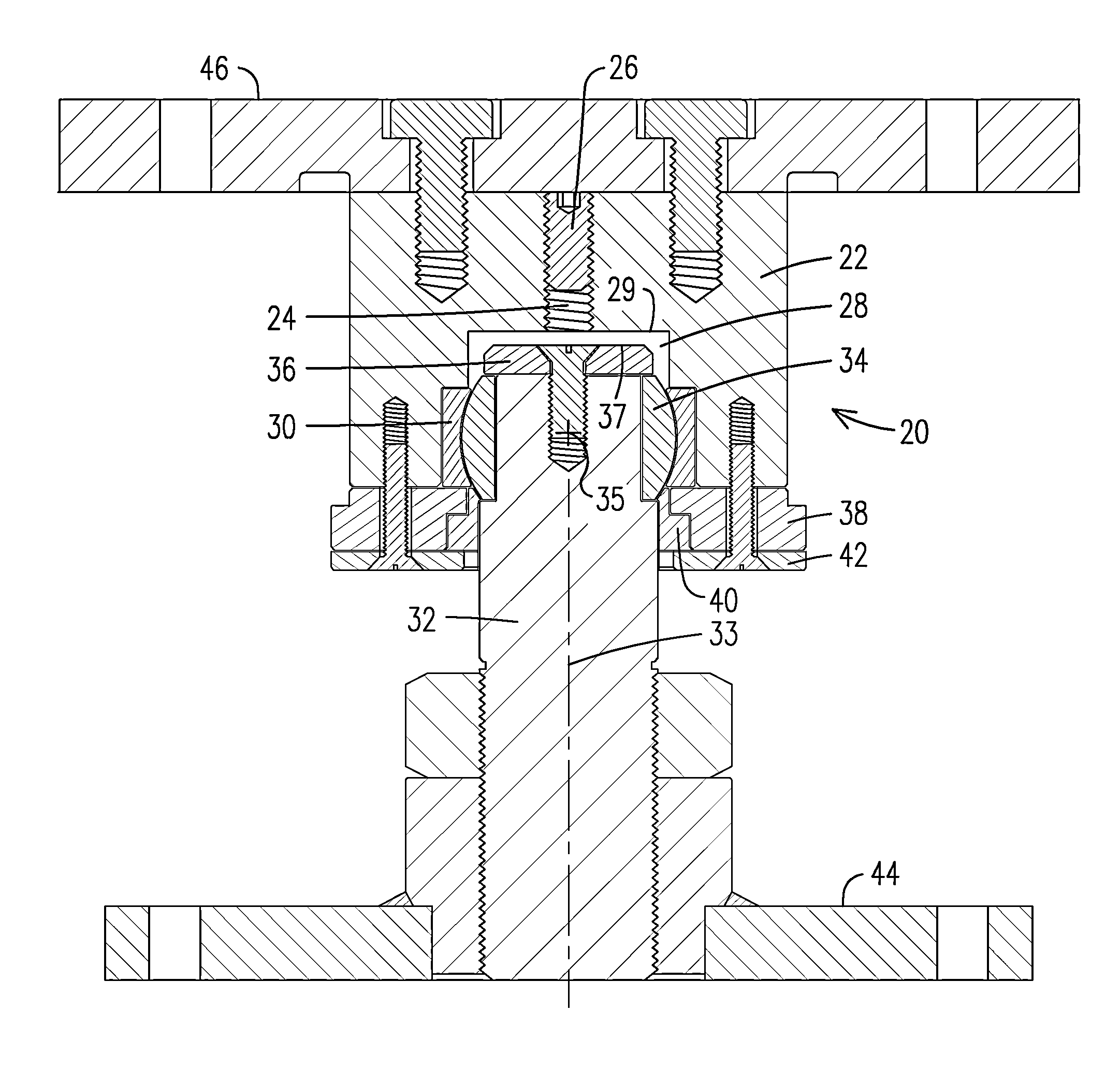
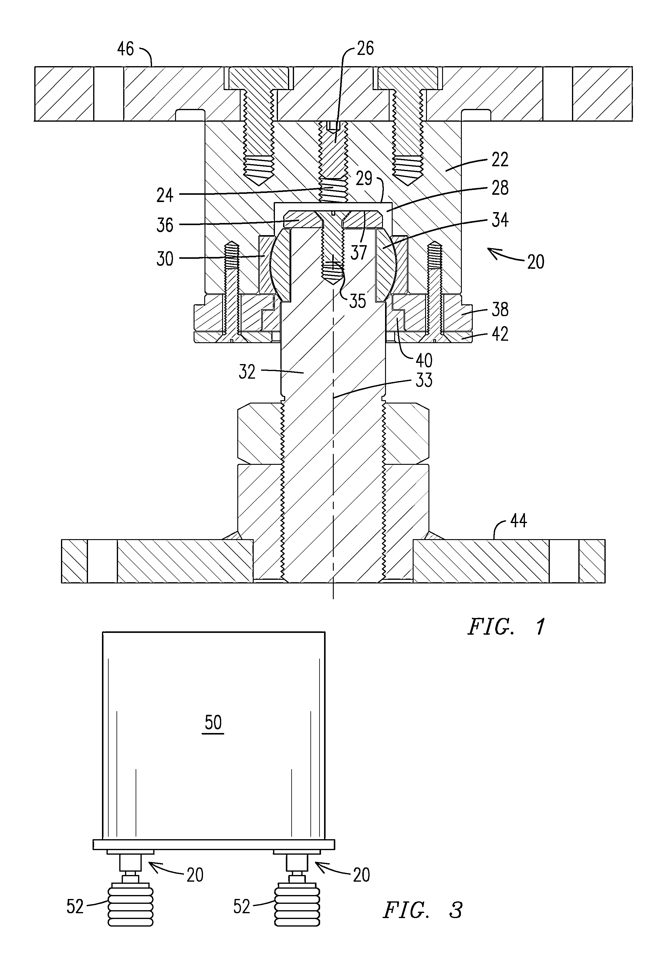
[0009]FIG. 1 is a side sectional view of a damping bearing assembly 20 according to aspects of an embodiment of the invention. A bearing housing 22 may have a threaded bore 24 leading to a damping fluid chamber 28 defined by clearance between an end of a support shaft 32 and the housing 22. A fluid sealing set screw 26 in the bore may provide access to the chamber 28, and may further provide a fluid pressure adjustment to a damping fluid therein. Herein “damping fluid” includes viscous fluids, semi-fluids, gels, and especially greases. The fluid used in tests of the invention described herein is an aluminum complex automotive / machine grease called Permalube™ Red, which has a National Lubricating Grease Institute (NLGI) consistency number of 2. The consistency of the damping fluid may be selected in combination with designing the shape and size of the damping fluid chamber 28 to cause a desired damping effect. The damping fluid chamber 28 is a void defined between inner surfaces of t...


PUM


Abstract

A damping bearing (20) including an inner ball portion (34) attached to an end of a support shaft (32), and an outer collar portion (30) attached to a housing (22) for rotation of the housing relative to the support shaft about a center point. A chamber (28) for a damping fluid such as grease is defined by clearance between the end of the shaft and the housing. The fluid chamber has opposed bounding surfaces (29, 37) that are non-spherical about the center of rotation so that the chamber changes shape upon rotation of the bearing, thus shifting damping fluid across the chamber. The chamber may be a flat cylindrical void normal to a centerline (33) of the shaft. It may provide only enough clearance for less than ±10 of relative rotation between the housing and shaft. A set-screw (26) may pressurize the fluid in the chamber.

Description

[0001]This application claims benefit of the 9 Jul. 2012 filing date of U.S. provisional patent application No. 61 / 669,304.FIELD OF THE INVENTION[0002]The invention relates to bearings that damp motion between a shaft and a housing, and particularly to bearings that damp oscillations of an object supported on legs or columns.BACKGROUND OF THE INVENTION[0003]An expression of the ability of a structure to dissipate kinetic energy when subjected to harmonic motion is termed “damping”. Most structures have an inherent ability to damp. It is an engineering practice to associate a level of damping with a particular form, material, construction method, or level of stress of a structure. If a structure can be shown to dissipate more kinetic energy than would normally be attributed to that type of structure, then there may be a reduction in loading for certain types of forces. This, in turn, allows a reduction in the strength requirement of the structure, and thus a cost saving.[0004]An elec...

Claims


Application Information

Patent Timeline
IPC IPC(8): F16F9/32F16M11/06
CPCF16M11/06F16F9/3207F16M7/00F16C23/043F16C27/02H01F27/06Y10T403/32614Y10T403/32704Y10T403/32729F16C11/068
Inventor KHAN, KAMRANREISINGER, HELMUT
Owner SIEMENS ENERGY GLOBAL GMBH & CO KG
Why Eureka
Try Eureka