Generating indirection maps for texture space effects

a technology of indirection and texture space, applied in the field ofgraphics rendering, can solve the problems of difficult or even impossible to create a three-dimensional model flat, difficult or even impossible to realistically model these sub-surface scattering properties, and achieve the effect of no loss of accuracy and without producing undesirable artifacts

Active Publication Date: 2015-07-02
NVIDIA CORP
View PDF8 Cites 17 Cited by
  • Summary
  • Abstract
  • Description
  • Claims
  • Application Information

AI Technical Summary

Benefits of technology

[0009]For coordinate locations that correspond to a region bounded by the contiguous two-dimensional representation, the indirection map is mapped to an unchanged position in the texture map. In contrast, when the coordinate location lies in a region outside the contiguous two-dimensional representation, but falls within pre-determined projected regions, the indirection map is mapped to an alternate, pre-determined position i

Problems solved by technology
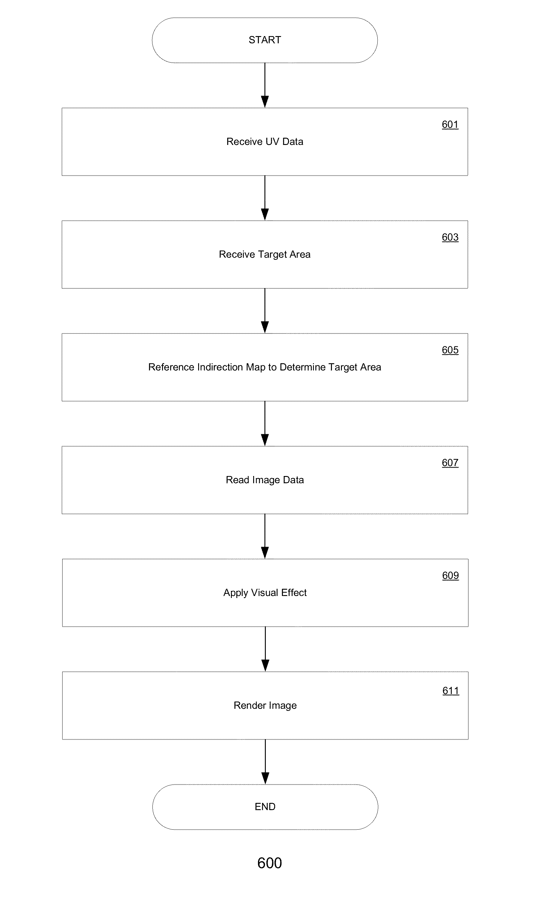
In contrast, rendering of objects that exhibit sub-surface scattering properties can be particularly complicated to perform realistically.
Realistically modeling these sub-surface scattering properties is difficult because of these particular effects.
However, it is often difficult or even impossible to create a flat representation of a three-dimensional model that will map completely as a single contiguous two dimensional region without artificial seams.
This causes undesirable artifacts in the rendered two dimensional image such as unexpected and/or undesirable lines or incongruous lighting along the surface of objects.
However, super-imposing additional layers would require additional time and labor, even in some instances may not be poss

Method used


Image

  • Generating indirection maps for texture space effects
  • Generating indirection maps for texture space effects
  • Generating indirection maps for texture space effects

Examples


Embodiment Construction

[0018]Reference will now be made in detail to the preferred embodiments of the claimed subject matter, a method and system for the use of a radiographic system, examples of which are illustrated in the accompanying drawings. While the claimed subject matter will be described in conjunction with the preferred embodiments, it will be understood that they are not intended to limit these embodiments. On the contrary, the claimed subject matter is intended to cover alternatives, modifications and equivalents, which may be included within the spirit and scope as defined by the appended claims.

[0019]Furthermore, in the following detailed descriptions of embodiments of the claimed subject matter, numerous specific details are set forth in order to provide a thorough understanding of the claimed subject matter. However, it will be recognized by one of ordinary skill in the art that the claimed subject matter may be practiced without these specific details. In other instances, well known meth...


PUM


Abstract

Embodiments of the present invention are directed to a novel approach for realistically modeling sub-surface scattering effects in three-dimensional objects of graphically rendered images. In an embodiment, an indirection map is generated for an image by analyzing the triangle mesh of one or more three-dimensional objects in the image and identifying pairs of edges between adjacent triangles in the mesh that have the same spatial locations in the three-dimensional representations, but which have different locations in the texture map. For each of these edges, the opposite triangle in each pair is projected into their corresponding edge's two-dimensional space. This allows samples which cross a seam in the two dimensional representation that would otherwise sample out into invalid data to be redirected to the spatially correct region of the texture and generate consistent results with non-seam areas.

Description

BACKGROUND OF THE INVENTION[0001]In the field of graphics rendering, objects in computer generated graphics are typically rendered to account only for the interaction of light at the surface of the object. For most opaque objects, this can be performed with little to no perceivable loss of realism. In contrast, rendering of objects that exhibit sub-surface scattering properties can be particularly complicated to perform realistically. These objects typically include those consisting of materials—such as skin, wax, ice, marble, jade, etc.—that naturally allow some light penetration at the surface of the material. Some of the penetrating light is absorbed, while the remaining portion subsequently scatters (diffuses) and brightens the immediately surrounding sub-surface area.[0002]Realistically modeling these sub-surface scattering properties is difficult because of these particular effects. Often, the effect is approximated by mapping the surface of three-dimensional object (typically...

Claims


Application Information

Patent Timeline
IPC IPC(8): G06T17/20G06T15/04
CPCG06T17/20G06T2210/56G06T15/04
Inventor MAGDER, LUCASTHOMPSON, MICHAELSHARIF, ZOHIRUL
Owner NVIDIA CORP
Why Eureka
Try Eureka