N-node virtual link trunking (VLT) systems management plane

a virtual link and management plane technology, applied in data switching networks, data switching details, high-level techniques, etc., can solve problems such as network loops, network redundancy links with stp, and network links that are underutilized

Active Publication Date: 2015-07-02
DELL PROD LP
View PDF3 Cites 40 Cited by
  • Summary
  • Abstract
  • Description
  • Claims
  • Application Information

AI Technical Summary

Problems solved by technology

Although having redundant links is helpful for failover situations, it creates network loops, which can be fatal to networks.
Thus, networks using redundant links with STP have links that are underutilized.
Because many of the links are placed into an inactive state by the STP, the network capacity is underutilized.
While this protocol allows for more links to be used for forwarding, it still suffers from the limitation of having a loop-free active topology for any given VLAN.
It must be noted, however, that the current various implementations of link aggregation have serious limitations.
Extending beyond two switches significantly adds complexity in connections, configuration, and operation.
For example, it is relatively simple to synchronize data between two devices, but it becomes significantly more complex to synchronize between multiple devices.
While running in such as primary-secondary configuration is easy to manage, it does not efficiently utilize network resources.
Third, limiting the number of switches that form the logical switch group does not provide a readily scalable solution.
Also, clients wanting to extend their current link aggregation system cannot do so because new each switch or pair of switches forms a new domain rather than simply extending an existing domain.
Thus, increasing the system involves adding separate link aggregation switch groups that must be separately managed, configured, and operated—needlessly adding complexity and administrative overhead.
Fourth, when pairing switches, vendors generally require that the devices be the same.
However, requiring like switches is rarely the best for clients.
Thus, current multi-chassis link systems inhibit cost effective equipment migration plans.

Method used


Image

  • N-node virtual link trunking (VLT) systems management plane
  • N-node virtual link trunking (VLT) systems management plane
  • N-node virtual link trunking (VLT) systems management plane

Examples


example 1

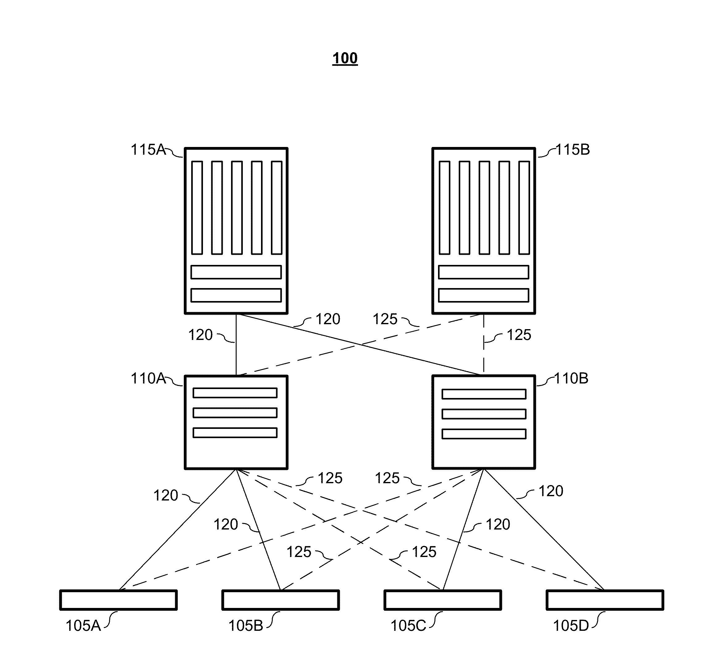
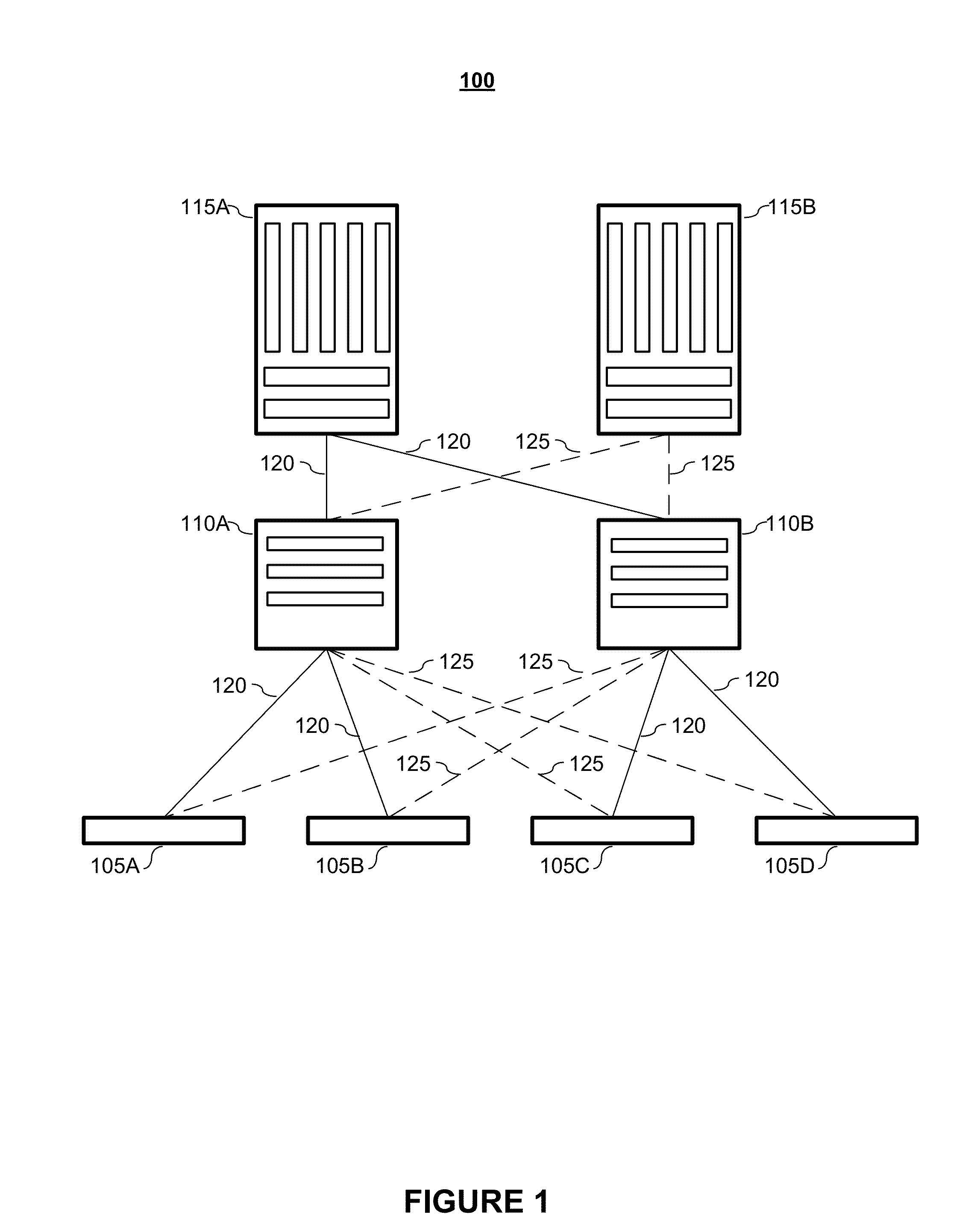
[0232]FIG. 13 depicts an example embodiment of an N-Node VLT system 1300 according to embodiments of the present invention. Depicted in FIG. 13 are four nodes N1 (1305-1), N2 (1305-2), N3 (1305-3), and N4 (1305-4), which form a 4-node VLT system 1320.

[0233]In forming the VLT system, the nodes are connected via a plurality of links 1325. These links may be referred to, interchangeably, as inter-node links (INLs), inter-chassis links (ICLs), or Virtual Link Trunk Interfaces (VLTIs). As shown in the embodiment depicted in FIG. 13, the nodes (N1-N4) are connected in a full mesh. While the depicted embodiment is a physical full mesh, it shall be noted that the nodes may be in a logical full mesh.

[0234]Also depicted in FIG. 13 are a number of VLT LAGs. External node E11310-1 has three links, which terminate on nodes N1, N3, and N4. These three links together form a VLT LAG, namely VLT11315-1. External node E21310-2 has four links that together form VLT21315-2. These links terminate on nod...

example 2

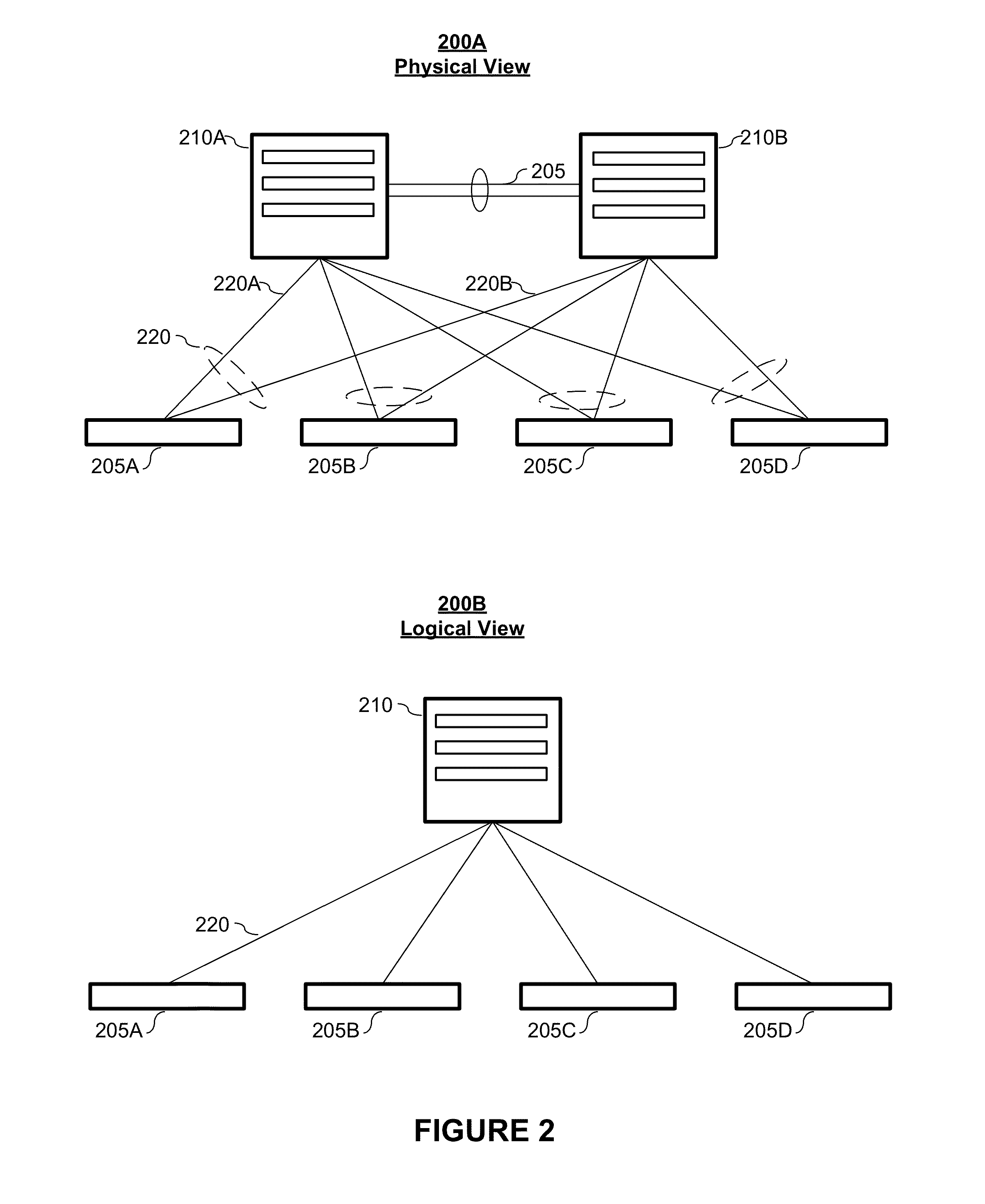
[0245]FIG. 14 depicts an example embodiment of an N-Node VLT system 1400 according to embodiments of the present invention. The system depicted in FIG. 14 has four nodes N1 (1405-1), N2 (1405-2), N3 (1405-3), and N4 (1405-4), which form a 4-node VLT system 1420. The embodiment depicted in FIG. 14 is the same configuration as in FIG. 13. Thus, it has the same VLT memberships, the same assigned nodes, and the same egress mask.

[0246]In embodiments, using the system 1400 depicted in FIG. 14 as an example, the handling of broadcast / unknown unicast packets may be processed as follows. First, external node E1 (1410-1) sends (1450) a broadcast packet to node N3 (1405-3). Node N3 (1405-3) floods (1455) the broadcast packets to all its local ports including all its ICL ports. The nodes N1, N2, and N4 flood (1460) the packets to their local ports based on their port blocks. Note that traffic ingressing on ICL(N3-N2) on node N2 is allowed to exit / egress on VLT3, as node N2 is the assigned node ...


PUM


Abstract

Aspects of the present invention include an N-Node virtual link trunking (VLT) system comprising a set of N nodes collectively provide a logical fabric-level view that is consistent across the set of N nodes. Embodiments of the N-Node VLT system comprise a control plane mechanism to provide Layer 2 multipathing between access network devices (switches or servers) and the core network. The N-Node VLT system provides a loop-free topology with active-active load-sharing of uplinks from access to the core. Accordingly, the N-Node VLT system eliminates the disadvantage of Spanning Tree Protocol (STP) (active-standby links) by allowing link aggregation group (LAG) terminations on multiple separate distribution or core switches and also supporting a loop-free topology. Additional benefits of an N-Node VLT system include, but are not limited to, higher resiliency, improved link utilization, and improved manageability of the network.

Description

CROSS-REFERENCE TO RELATED APPLICATIONS[0001]This patent application is related in subject matter to co-pending and commonly-owned U.S. patent application. Ser. No. ______, filed on Dec. 27, 2013, entitled “N-Node Virtual Link Trunking (VLT) Systems and Methods,” and listing Anoop Ghanwani, Krishnamurthy Subramanian, Pathangi Janardhanan, Shivakumar Sundaram, and Mohnish Anumala as inventors (Docket No. DC-101843 (20110-1804)), which patent document is incorporated by reference herein in its entirety and for all purposes.[0002]This patent application is also related in subject matter to co-pending and commonly-owned U.S. patent application. Ser. No. ______, filed on Dec. 27, 2013, entitled “N-Node Virtual Link Trunking (VLT) Systems Control Plane,” and listing Mohnish Anumala and Jeyasubramanian Irungola Pillai as inventors (Docket No. DC-101844 (20110-1805)), which patent document is incorporated by reference herein in its entirety and for all purposes.[0003]This patent application...

Claims


Application Information

Patent Timeline
Patent Type & Authority Applications(United States)
IPC IPC(8): H04L12/24H04L12/709H04L45/16H04L45/243H04L45/586
CPCH04L41/083H04L41/12H04L45/245H04L12/18H04L45/586H04L45/16H04L41/0663Y02D30/50H04L41/122
Inventor ANUMALA, MOHNISHPILLAI, JEYASUBRAMANIAN IRUNGOLAAZZI, GEORGE
Owner DELL PROD LP
Why Eureka
Try Eureka