Spinal fusion system

a spinal fusion and spinal technology, applied in the field of spinal fusion systems, spinal implants and delivery systems, can solve the problems of time-consuming and labor-intensive spinal fusion procedures, and the surgical outcomes of patients are not always as desired or hoped

Active Publication Date: 2015-07-23
SPINEWAVE
View PDF8 Cites 62 Cited by
  • Summary
  • Abstract
  • Description
  • Claims
  • Application Information

AI Technical Summary

Problems solved by technology

Spinal fusions can be time intensive to perform, and surgical outcomes for patients are not always as desired or hoped for.

Method used


Image

  • Spinal fusion system
  • Spinal fusion system
  • Spinal fusion system

Examples


Embodiment Construction

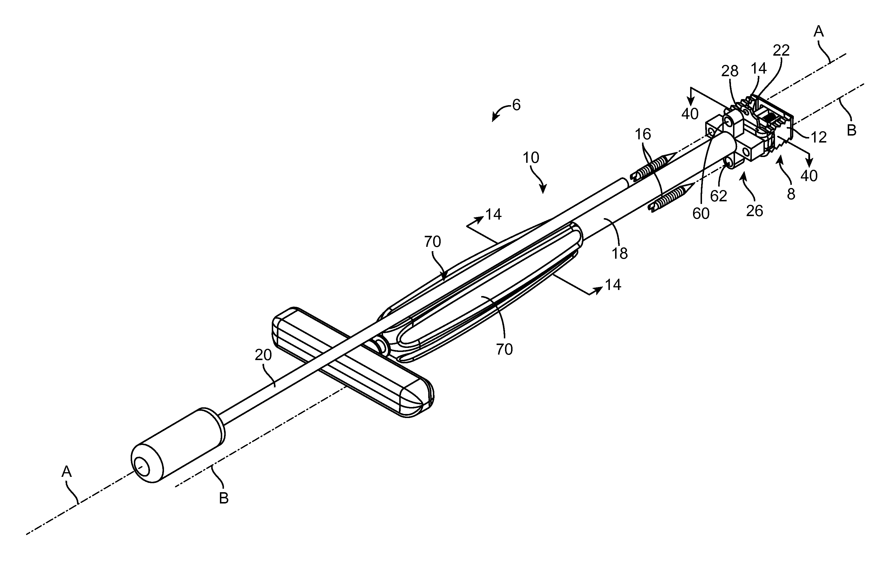
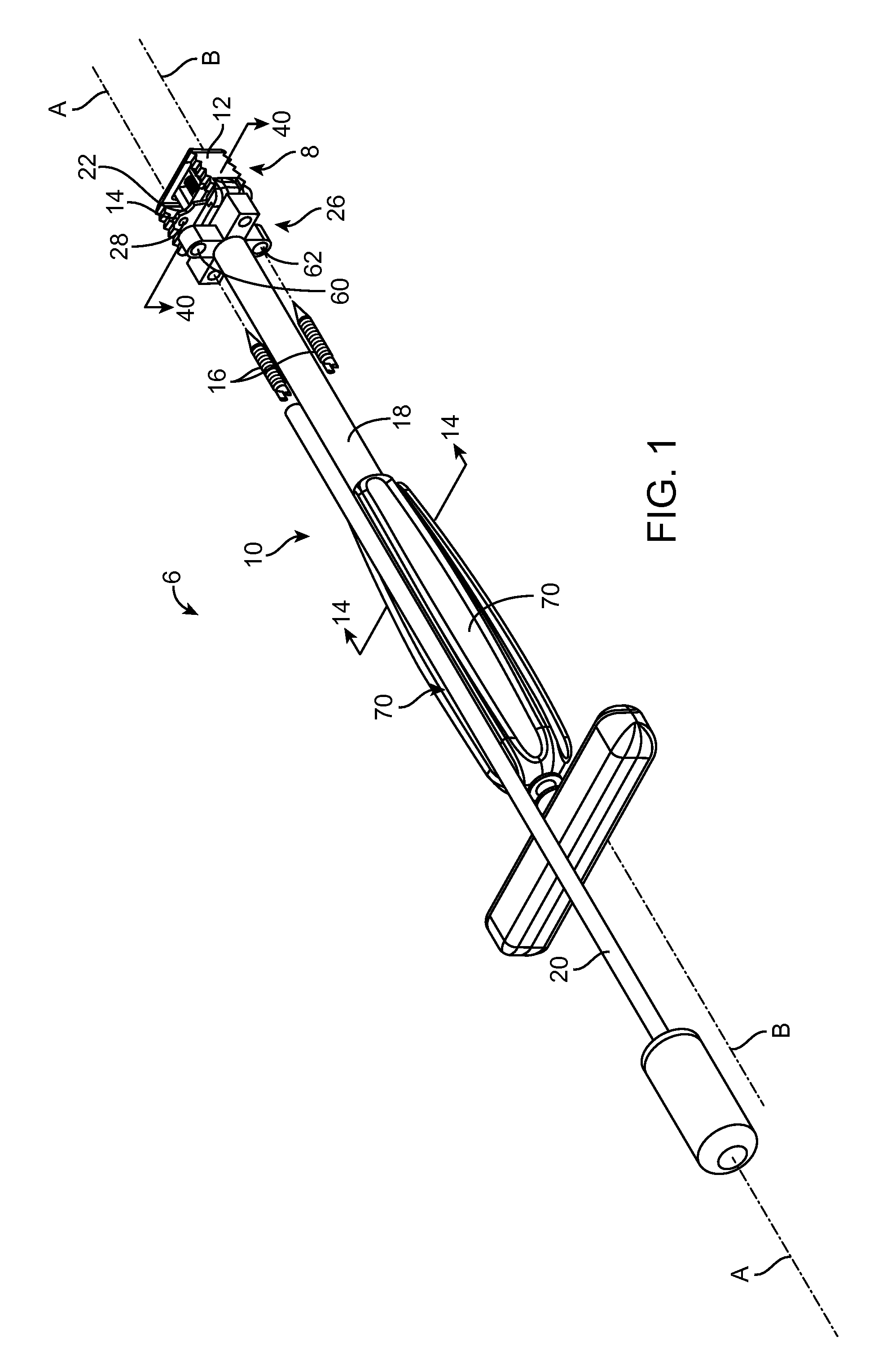
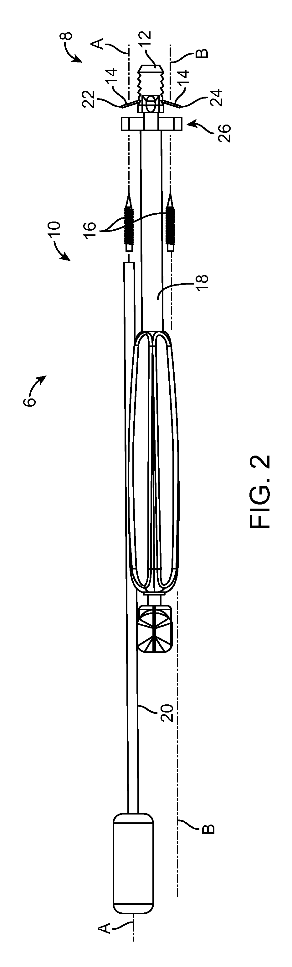
[0075]Referring to FIG. 1, in one embodiment, a spinal fusion system 6 may include a spinal implant 8 and an implantation tool set 10 for delivering and implanting spinal implants in a spinal column to treat a spinal condition. In one embodiment, the spinal implant 8 includes an interbody fusion cage 12, an anterior fixation plate 14, and bone screws 16 that are received by the fixation plate. The implantation tool set 10 includes an implanter 18 and a screw driver 20.

[0076]The cage 12 is designed to be implanted in a disc space between a superior vertebra and an inferior vertebra and to act as a fusion cage system to fix and fuse the superior and inferior vertebrae together. The cage 14 is delivered to the disc space via the implanter 18. When implanted in the disc space, the cage 12 abuts against the superior plate of the inferior vertebra and the inferior plate of the superior vertebra

[0077]The plate 14 includes a superior blade 22 and an inferior blade 24. The plate 14 is design...


PUM


Abstract

A spinal fusion system may include an interbody fusion cage, a fixation plate, and an implanter. The interbody fusion cage may include a proximal region, a distal region opposite the proximal region, a superior region, an inferior region opposite the superior region, and an open volume between the proximal and distal regions. The superior and inferior regions are located between the proximal and distal regions and are configured such that, when the interbody fusion cage is implanted in the disc space, the superior region contacts the inferior end plate and the inferior region contacts the superior end plate. The fixation plate is receivable in the open volume of the interbody fusion cage and includes a superior blade and an inferior blade. At least one of the blades includes a first opening defined therein. The fixation plate is displaceable between a non-deployed state and a deployed state.

Description

CROSS-REFERENCE TO RELATED APPLICATIONS[0001]This application claims priority to U.S. Provisional Patent Application Ser. Nos. 61 / 928,799, entitled “STAND-ALONE CAGE SYSTEM: INTEGRATED ANCHOR / SCREW DESIGN,” filed on Jan. 17, 2014; 61 / 949,015, entitled “SYSTEM AND METHOD OF IMPLANTING A SPINAL IMPLANT,” filed on Mar. 6, 2014; and 61 / 969,695 entitled “SPINAL FUSION SYSTEM,” filed Mar. 24, 2014. The full disclosures of the above-listed patent applications are hereby incorporated by reference herein.FIELD[0002]Aspects of the present disclosure relate to systems and methods for the treatment of spinal conditions. More specifically, the present disclosure relates to spinal implants and delivery systems for, and methods of, delivering and implanting spinal implants in a spinal column in the treatment of a spinal condition, including spinal fusion treatments.BACKGROUND[0003]Spinal fusions are commonly performed on patients suffering from pain and dysfunction stemming from spinal trauma, deg...

Claims


Application Information

Patent Timeline
Patent Type & Authority Applications(United States)
IPC IPC(8): A61F2/44A61F2/30A61F2/46
CPCA61F2/447A61F2/4611A61F2002/4623A61F2/30749A61F2/4657A61F2/4455A61B17/86A61F2002/30507A61F2002/30578A61F2002/30579A61F2002/4627A61F2/4603A61F2/4684
Inventor TANAKA, SHIGERULIOU, EDWARDSMITH, JEFFREY D.SCHUMMERS, DAVID MICHAELJONES, BRADKUNWAR, SANDEEPWEBER, PETERMCCORMACK, BRUCE M.
Owner SPINEWAVE
Why Eureka
Try Eureka