Angled Bullet-Nose Banana Cage

a bullet-nose banana and cage technology, applied in the field of angled bullet-nose banana cages, can solve the problems of inability to fully integrate the cage into the disc space, inability to adjust the cage,

Inactive Publication Date: 2012-11-01
DEPUY SYNTHES PROD INC
View PDF5 Cites 56 Cited by
  • Summary
  • Abstract
  • Description
  • Claims
  • Application Information

AI Technical Summary

Benefits of technology

[0041]Thus, the advantage of this invention is that the pronounced nose allows the cage designer to

Problems solved by technology

In particular, it has been found that when the direction of the slope of the pronounced nose is in-line with the curvature of the banana cage (see 30 degree nose angle of FIG. 1), the initial insertion of this cage into the disc space requires excessive force.
This is because the nose angle

Method used


Image

  • Angled Bullet-Nose Banana Cage
  • Angled Bullet-Nose Banana Cage
  • Angled Bullet-Nose Banana Cage

Examples


Embodiment Construction

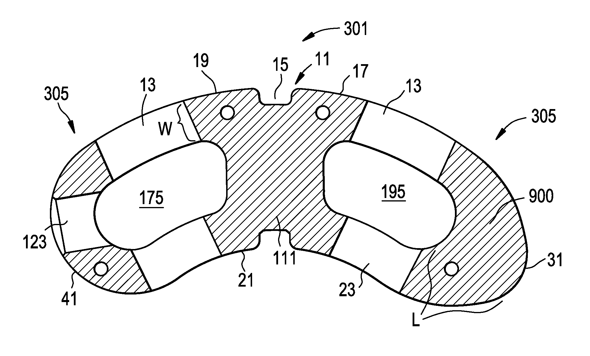
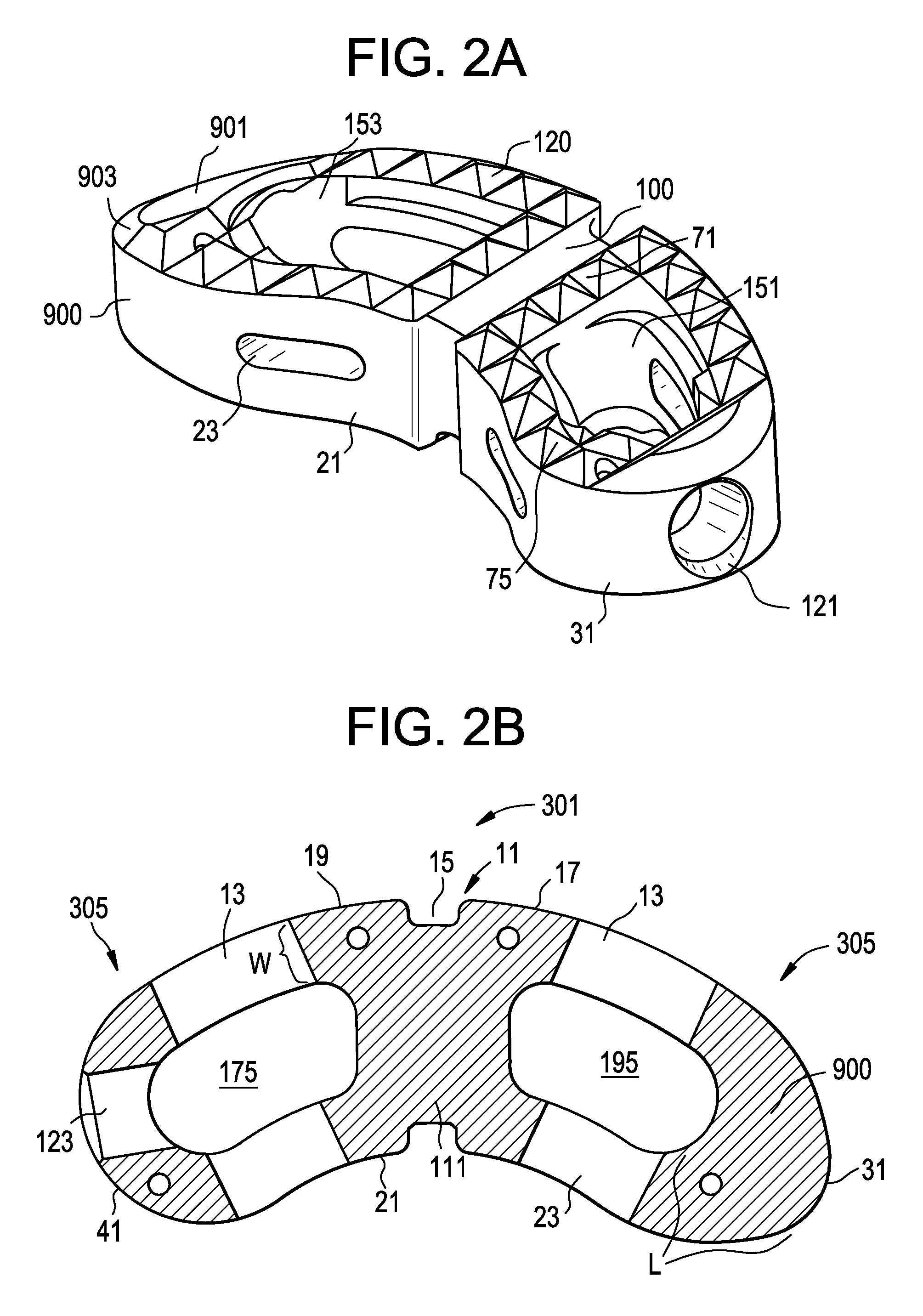
[0046]For the purposes of the present invention, the banana cage is considered to have a “pronounced nose” when the nose has a length L that is at least 50% longer than the width W of the anterior wall of the cage, The width W of the anterior wall and the length L of the nose of one particular cage are shown in FIG. 2B.

[0047]In this application, the terms “pronounced nose” and “bulleted nose” are used interchangeably.

[0048]Preferably, the nose further has upper and lower substantially planar sloped portions, defining a leading direction.

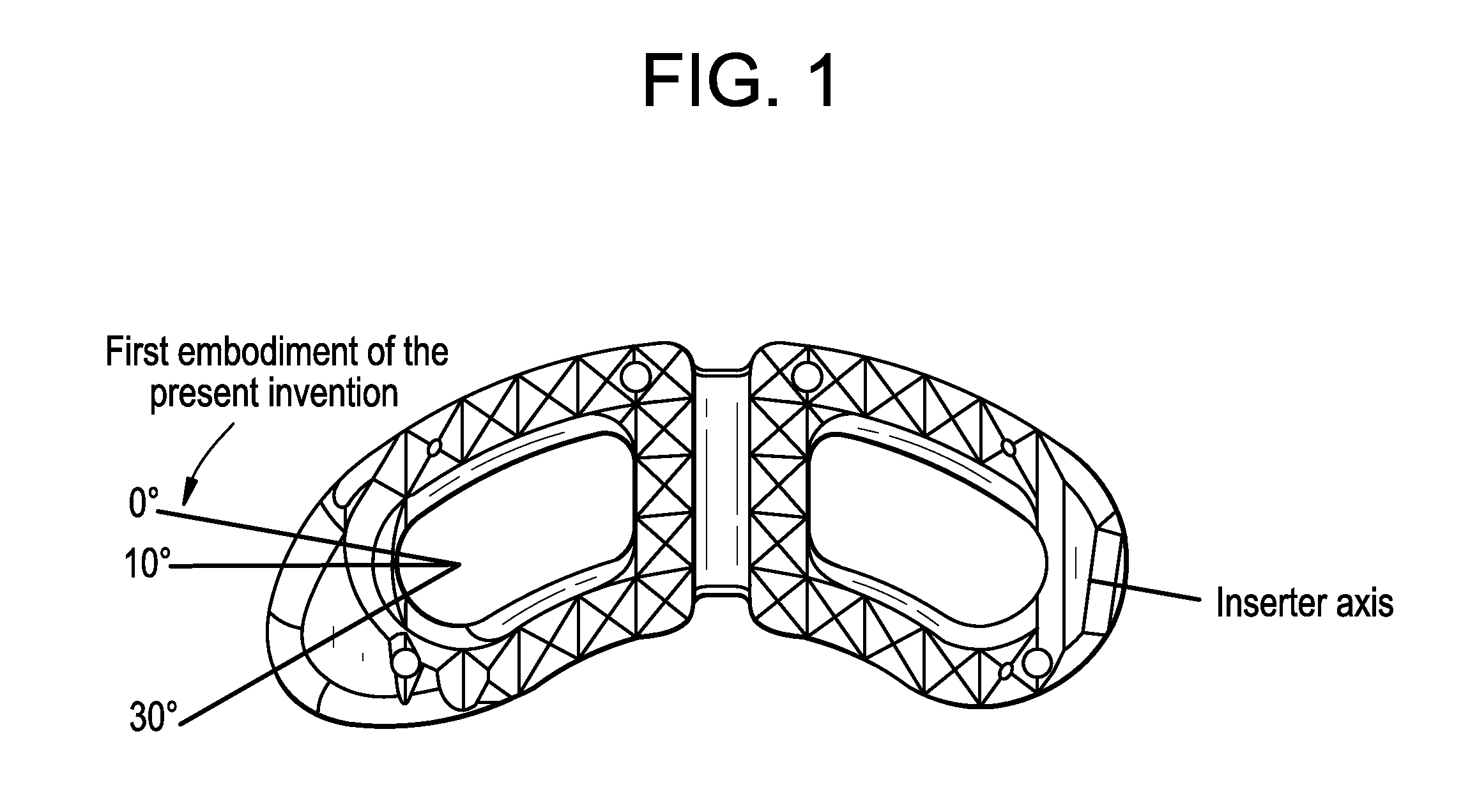
[0049]Preferably, the sloped portions of the nose define a total taper angle α therebetween of between 25 and 45 degrees, more preferably between 30 and 40 degrees, more preferably between 35 and 40 degrees. At larger angles, the nose is more blunt and so does not easily distract a collapsed disc space. At smaller angles, the length of the nose must be undesirably long, thereby making the cage unwieldy.

Therefore, in accordance with the present invent...


PUM


Abstract

A banana-shaped cage adapted for use as an intervertebral fusion cage, wherein the leading direction of the nose of the banana cage is substantially in-line with the angle of the inserter shaft that inserts the cage into the disc space. It has been found that insertion of this cage requires lower insertion forces than the conventional cage whose leading direction substantially follows the arc of the banana curve.

Description

BACKGROUND OF THE INVENTION[0001]The leading cause of lower back pain arises from rupture or degeneration of lumbar intervertebral discs. Pain in the lower extremities is caused by the compression of spinal nerve roots by a bulging disc, while lower back pain is caused by collapse of the disc and by the adverse effects of articulation weight through a damaged, unstable vertebral joint. One proposed method of managing these problems is to remove the problematic disc and replace it with a porous device that restores disc height and allows for bone growth therethrough for the fusion of the adjacent vertebrae. These devices are commonly called “fusion devices”.[0002]U.S. Pat. No. 4,743,256 (“Brantigan”) discloses an improved surgical method for eliminating spinal back pain caused by ruptured or degenerated vertebral discs by spanning the disc space between adjacent vertebrae with rigid fusion devices, or “cages”, having surfaces facilitating bone ingrowth and bottomed on prepared sites ...

Claims


Application Information

Patent Timeline
IPC IPC(8): A61F2/44
CPCA61F2/442A61F2/4465A61F2/4611A61F2/4684A61F2002/2835A61F2002/30062A61F2310/00293A61F2002/4475A61F2310/00023A61F2310/00179A61F2310/00203A61F2310/00239A61F2002/30308A61F2002/30593
Inventor KALLURI, PRAKASAMRUSBARSKY, CHRISTINEMARTIN, THOMASHOWE, JONATHAN
Owner DEPUY SYNTHES PROD INC
Why Eureka
Try Eureka