Liquid droplet detecting device, inkjet recording device incorporating same, and liquid droplet detection method

US20150224802A1Inactive Publication Date: 2015-08-13RICOH KK

Image

  • Liquid droplet detecting device, inkjet recording device incorporating same, and liquid droplet detection method
  • Liquid droplet detecting device, inkjet recording device incorporating same, and liquid droplet detection method
  • Liquid droplet detecting device, inkjet recording device incorporating same, and liquid droplet detection method

Examples


Embodiment Construction

[0043]Hereinafter, embodiments of an inkjet recording device and a liquid droplet detecting device will be described in detail with reference to the accompanying drawings. Wherever possible, the same reference numbers will be used throughout the drawings to refer to the same or like parts.

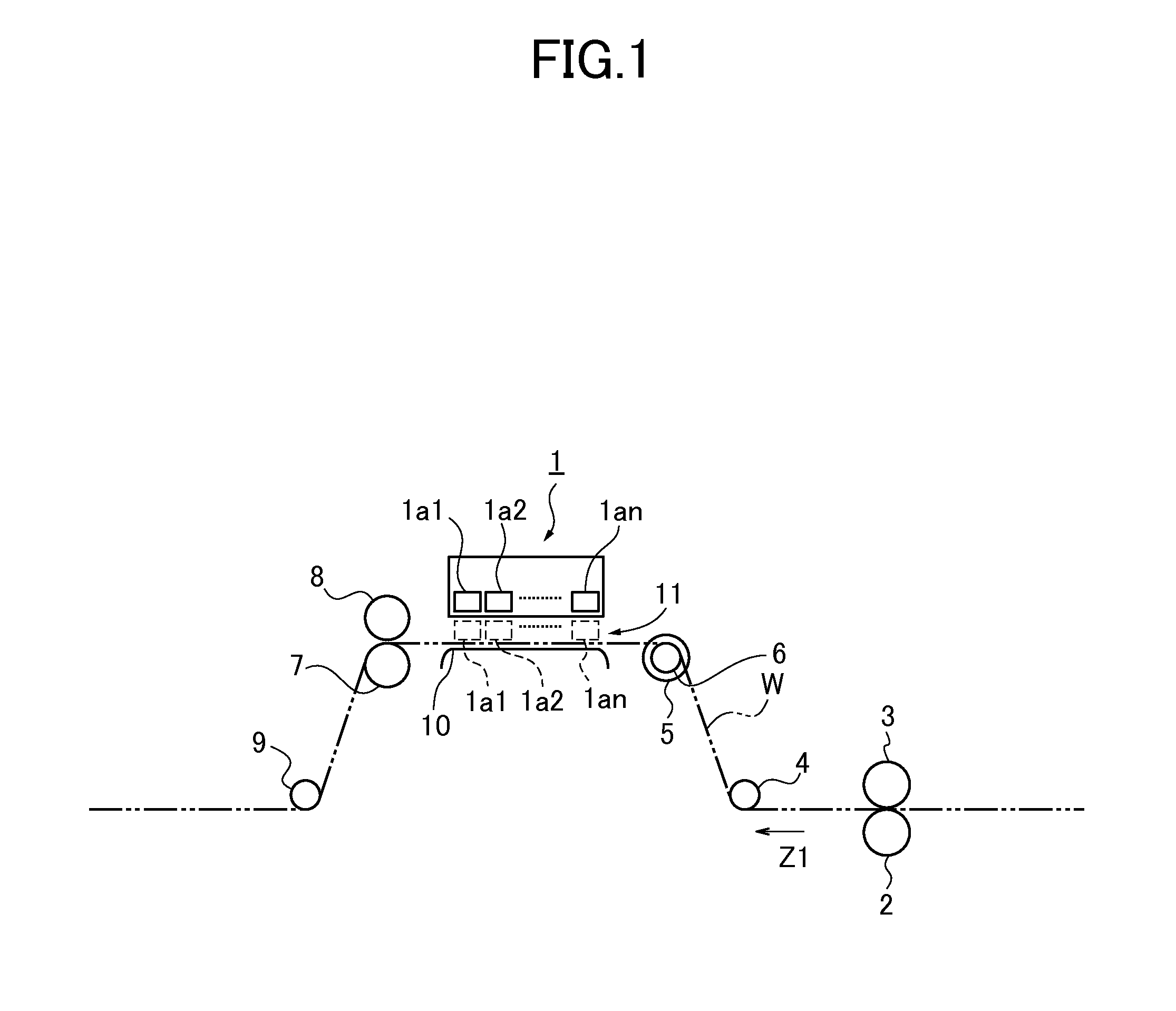
[0044]FIG. 1 schematically shows the structure of an inkjet recording device according to one embodiment. The inkjet recording device is also called as an image forming device or an inkjet printer.

[0045]In FIG. 1 the inkjet recording device comprises an inkjet head array 1, a paper feeding roller 2, a driven roller 3 rotated with the paper feeding roller 2, a tension roller 4, a driven roller 6 including an encoder 5 for detecting a feed amount of a paper W, a paper ejection roller 7, a driven roller 8 rotated with the paper ejection roller 7, and a tension roller 9 arranged in a paper conveying direction Z1. The paper ejection roller 7 is rotated by a not-shown drive motor.

[0046]A drive plate 10 i...


PUM


Abstract

A liquid droplet detecting device includes nozzles arranged in a paper width direction orthogonal to a paper conveying direction to discharge liquid droplets, a light emitting element provided on one side of the paper width direction to emit a light beam for liquid droplet detection, a light receiving element provided on the other side of the paper width direction to receive the light beam, a storage in which correspondence information on each of the nozzles and a scan position of the light beam when discharge of a liquid droplet from each of the nozzles is detected is stored, a controller to allow the light beam to scan according to the correspondence information, and a detector to determine presence or absence a liquid droplet discharged from each nozzle from an output of the light receiving element.

Description

CROSS REFERENCE TO RELATED APPLICATION[0001]The present application is based on and claims priority from Japanese Patent Application No. 2014-24086, filed on Feb. 12, 2014 and No. 2014-241398, filed on Nov. 28, 2014, the disclosure of which is hereby incorporated by reference in its entirety.BACKGROUND OF THE INVENTION[0002]1. Field of the Invention[0003]The present invention relates to a liquid droplet detecting device, an inkjet recording device incorporating such a device and a liquid droplet detection method.[0004]2. Description of the Related Art[0005]An inkjet recording device to form an image on a paper by discharging ink from nozzles of recording heads is known. Nozzle discharge failure may occur in this device due to dried ink or entry of foreign matter and air bubbles.[0006]Such nozzle discharge failure results in deteriorating image quality. In view of this, there is a known inkjet recording device with a liquid droplet detector which determines presence or absence of ink...

Claims


Application Information

Patent Timeline
13 Aug 2015
Publication
US20150224802A1
IPC
B41J29/393
CPC
B41J29/393; B41J2/125; B41J2/16579; B41J2/16585; B41J25/34; B41J2/2142
Inventors
KAWAMICHI, GENICHIRO; MORINAGA, SHIGERU