Optical fiber vibration detection method, device and system

A technology of optical fiber vibration and detection device, applied in measurement device, measurement of ultrasonic/sonic/infrasonic waves, instruments, etc., can solve the problems of performance degradation, limited application range, low detection sensitivity, etc., and achieve the effect of improving sensitivity and efficiency

Inactive Publication Date: 2016-07-20
惠州市明光实业有限公司
View PDF4 Cites 4 Cited by
  • Summary
  • Abstract
  • Description
  • Claims
  • Application Information

AI Technical Summary

Problems solved by technology

[0005] What the OTDR detects is the synthetic signal of the vibration of the entire optical fiber. When detecting and locating the vibration source, the performance is severely degraded or even cannot work normally.
Moreover, the detection sensitivity of OTDR is very low, because the backscattered light generated is very weak, so the distributed optical fiber sensing system based on optical time domain reflection technology can only perform static measurement, and the application range is limited

Method used


Image

  • Optical fiber vibration detection method, device and system
  • Optical fiber vibration detection method, device and system
  • Optical fiber vibration detection method, device and system

Examples


Embodiment Construction

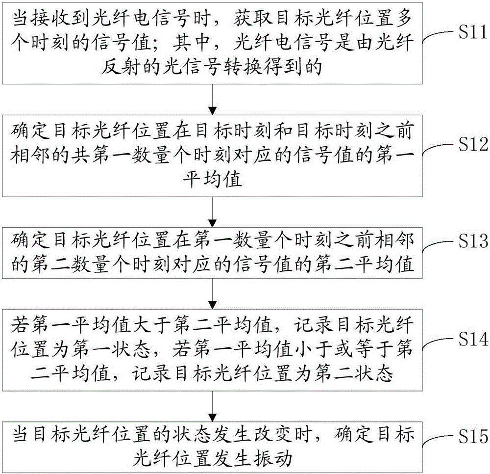
[0024] refer to figure 1 , a schematic flow chart of an embodiment of the optical fiber vibration detection method of the present invention, the method includes:

[0025] S11: When the optical fiber electrical signal is received, the signal values ​​at multiple time points at the position of the target optical fiber are obtained; wherein the optical fiber electrical signal is converted from an optical signal reflected by the optical fiber.

[0026] Optionally, the optical signal reflected by the optical fiber is the second optical signal formed and reflected by Rayleigh scattering of the first optical signal transmitted from the starting point of the optical fiber at various positions in the optical fiber.

[0027] Optionally, the optical fiber electrical signal is a digital electrical signal; wherein, the digital electrical signal is converted from an analog electrical signal, and the analog electrical signal is converted from an optical signal reflected by an optical fiber. ...


PUM


Abstract

The invention discloses an optical fiber vibration detection method, device and system. The method comprises the steps of: obtaining signal values of a plurality of moments at a target optical fiber position when an optical fiber electrical signal is received; determining a first average value of the signal values corresponding to a first number of moments from the target moment to the moments before and adjacent to the target moment at the target optical fiber position; determining a second average value of the signal values corresponding to a second number of moments before and adjacent to the first number of moments; if the first average value is larger than the second average value, recording the target optical fiber position as a first state; if the first average value is smaller than or equal to the second average value, recording the target optical fiber position as a second state; and determining that the vibration happens at the target optical fiber position when the state of the target optical fiber position changes. By means of the above mode, the precision and the efficiency of optical fiber vibration positioning can be improved.

Description

technical field [0001] The invention relates to the field of optical fiber communication, in particular to an optical fiber vibration detection method, device and system. Background technique [0002] Optical fiber is the abbreviation of optical fiber, which is a kind of fiber made of glass or plastic, which can be used as a light transmission tool, and the transmission principle is the total reflection of light. Most optical fibers must be covered by several layers of protective structures before use, and the coated cables are called optical cables. [0003] With the development of fiber optic technology, fiber optic vibration early warning systems have been extensively studied in recent years. Optical fiber vibration early warning is mainly to judge the vibration of the optical fiber by detecting the change of the signal in the optical fiber, so as to judge the vibration of the environment around the optical fiber. There are mainly two types of technologies, interference...

Claims


Application Information

Patent Timeline
Patent Type & Authority Applications(China)
IPC IPC(8): G01H9/00
CPCG01H9/004
Inventor 赵银凤刘博宇魏照聂鑫李建彬魏嘉
Owner 惠州市明光实业有限公司
Why Eureka
Try Eureka