Method of assembling a serial fan

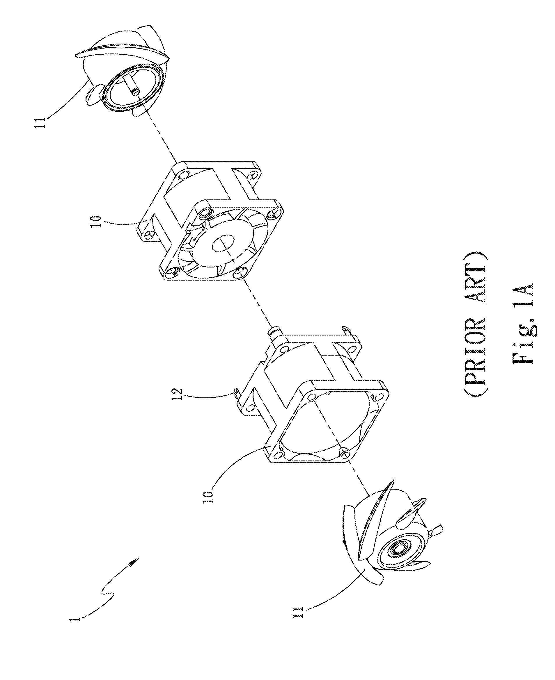
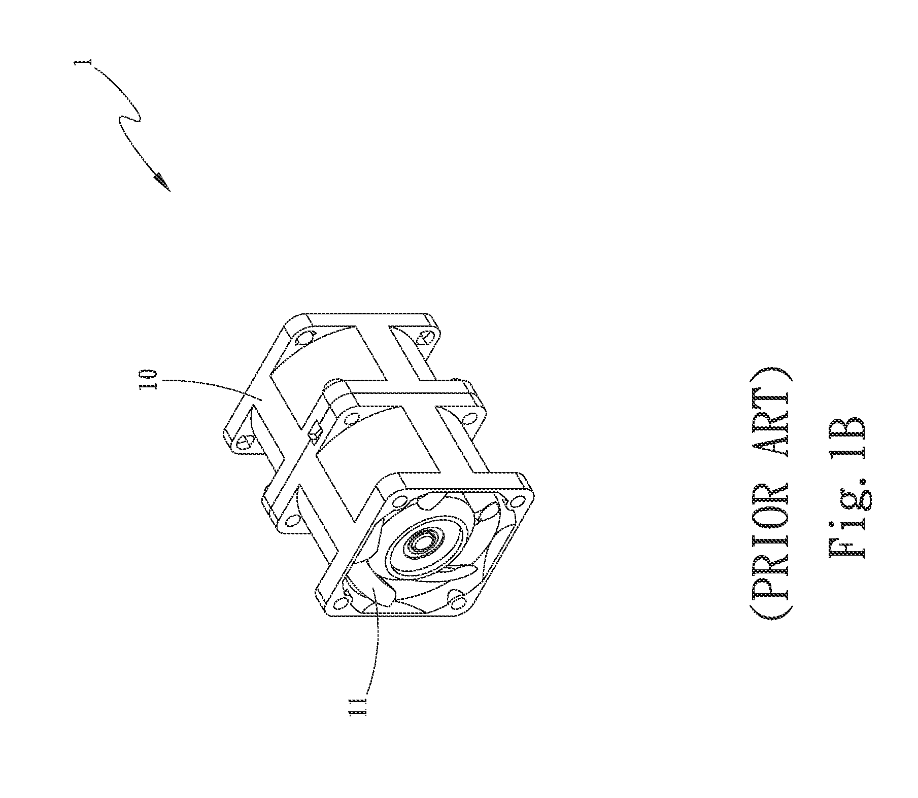
a technology of serial fans and assembly methods, which is applied in the direction of machines/engines, liquid fuel engines, forging/pressing/hammering apparatus, etc., can solve the problems of large heat produced by the internal electronic elements of various electronic devices, such as desktop computers, notebook computers, and inability to change the vibrating state of the serial fan, so as to reduce the vibration of the fan and quickly assembled together

Active Publication Date: 2015-08-20
ASIA VITAL COMPONENTS (CHINA) CO LTD
View PDF2 Cites 7 Cited by
  • Summary
  • Abstract
  • Description
  • Claims
  • Application Information

AI Technical Summary

Benefits of technology

[0010]According to the method of the present invention, after the first fan is connected to the union member via the first open side, the second fan can be connected to the union member via the first open side or the second open side. In either way, the first and the second fan, after being connected to the union member, are serially located in the receiving space in a manner ca

Problems solved by technology

It is known that internal electronic elements of various electronic devices, such as desktop computers, notebook computers and the like, will produce a large amount of heat during operation thereof.
With this assembling method, it is not able to change the serial fan's vibrating state.
Moreover, since the fan frames 10 in the conventional serial fan design are respectively formed as one single part, they are not able to effectively reduce the fan vibration.
In some worse condition, the vibration produced by the motor and the fan wheels 11 would interfere

Method used


Image

  • Method of assembling a serial fan
  • Method of assembling a serial fan
  • Method of assembling a serial fan

Examples


first embodiment

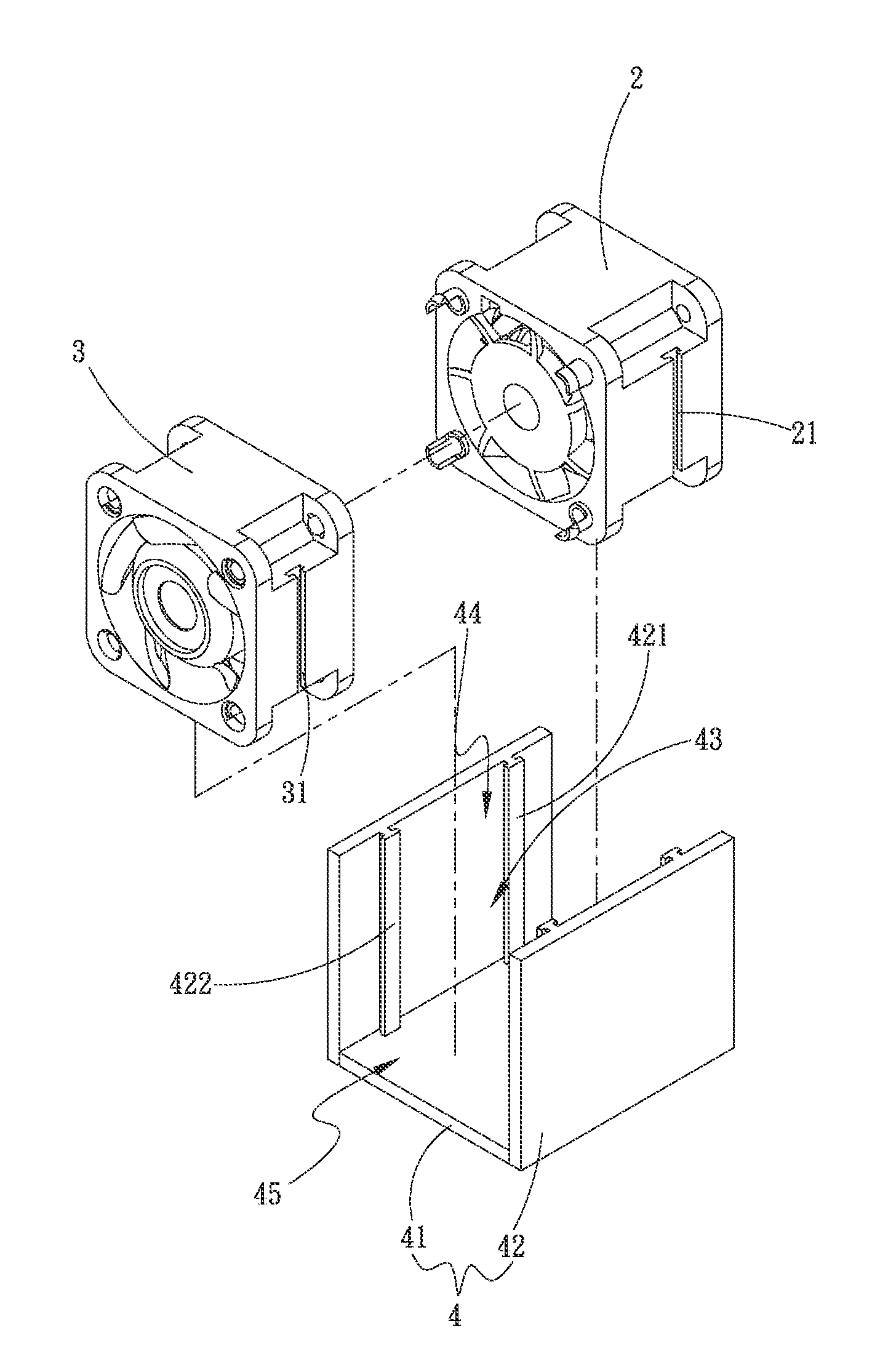
[0027]More specifically, in the first step S1 of the method of the present invention, a first fan 2 and a second fan 3 are provided. The first fan 2 includes a first connection section 21, and the second fan 3 includes a second connection section 31. In the first embodiment, the first and the second connection section 21, 31 are respectively illustrated as a channel. However, it is understood, in practical implementation of the present invention, the first and second connection sections 21, 31 are not necessarily limited to channels but can be otherwise slide rails, projected tongues or grooves.

[0028]In the second step S2, a union member is provided. The union member includes a bottom panel and two side panels upward extended from two lateral sides of the bottom panel, such that a receiving space is defined between the bottom panel and the two side panels. The receiving space has a top located opposite to the bottom panel and forming a first open side, and two axially opposite ends ...

second embodiment

[0036]And, while the third mating connection section 411 in the second embodiment is illustrated as slide rails, it is understood, in practical implementation of the present invention, the third mating connection section 411 is not necessarily limited to slide rails but can be otherwise channels, grooves or projected tongues.

[0037]In the third step S3 of the second embodiment, the first fan 2 is connected to the side panels 42 of the union member 4 via the first open side 44, and the second fan 3 is connected to the bottom panel 41 of the union member 4 via one of the two second open sides 45 with the third connection section 32 on the second fan 3 engaged with the third mating connection section 411 on the bottom panel 41 of the union member 4. In other words, the first fan 2 is connected to the union member 4 in a vertical direction relative to the union member 4, while the second fan 3 is connected to the union member 4 in a horizontal direction relative to the union member 4. Af...


PUM

PropertyMeasurementUnit
Timeaaaaaaaaaa

Abstract

A serial fan assembling method includes the steps of providing a first and a second fan; providing a union member having a bottom panel and two side panels, which together define a receiving space having a top forming a first open side and two axially opposite ends respectively forming a second open side; connecting the first fan to the side panels of the union member via the first open side; and connecting the second fan to the side panels of the union member via the first open side, or connecting the second fan to the bottom panel of the union member via one of the second open sides, so that the first and the second fan connected to the union member are serially located in the receiving space and connected to each other.

Description

FIELD OF THE INVENTION[0001]The present invention relates to a method of assembling a serial fan, and more particularly to a serial fan assembling method that effectively reduces the vibration produced by the assembled serial fan during operation thereof.BACKGROUND OF THE INVENTION[0002]People's reliance on various electronic devices increases with the constant progress in the electronic technology. It is known that internal electronic elements of various electronic devices, such as desktop computers, notebook computers and the like, will produce a large amount of heat during operation thereof. The produced heat must be timely guided off the electronic devices to avoid overheating of the electronic device. Therefore, most electronic devices are internally provided with a cooling fan for the devices to always operate at a predetermined working temperature.[0003]Please refer to FIGS. 1A and 1B. A serial fan 1 known in the electronic industrial field includes a plurality of size-identi...

Claims


Application Information

Patent Timeline
IPC IPC(8): F04D29/64
CPCF04D29/644F04D29/646F04D19/007F04D19/02F04D29/668F05D2230/51Y10T29/49327
Inventor LIU, WEN-HAO
Owner ASIA VITAL COMPONENTS (CHINA) CO LTD
Why Eureka
Try Eureka