Sealing element for a fluidic connection

Active Publication Date: 2015-08-20
AGILENT TECH INC
View PDF1 Cites 5 Cited by
  • Summary
  • Abstract
  • Description
  • Claims
  • Application Information

AI Technical Summary

Benefits of technology

[0037]According to an embodiment, the sealing element is configured to have a cylindrical outer surface portion having a constant diameter in the longitudinal direction; and the recess of the coupling element comprises a cylindrical inner surface portion, wherein the connected state the cylindrical inner surface portion of the coupling element and the cylindrical outer surface portion of the sealing element at least partially overlap in longitudinal direction. According to an embodiment, in the connected state the cylindrical inner surface portion of the coupling element and the cylindrical outer surface portion of the sealing element are radially spaced from each other, at least if no pressure is exerted on the sealing element in the longitudinal direction, e.g. into the recess of the coupling element. This may allow for an easier insertion of the sealing element into the recess of the coupling element. Further, if retaining elements of the sealing element are provided in the recess of the sealing element in a longitudinal range of the sealing element over which the cyli

Problems solved by technology

Sealingly coupling a tubular element with a coupling element may be a complex task, in particular if the diameter of the tubular element is small or if the tubula

Method used


Image

  • Sealing element for a fluidic connection
  • Sealing element for a fluidic connection
  • Sealing element for a fluidic connection

Examples


Example

[0070]The illustration in the drawings is schematic.

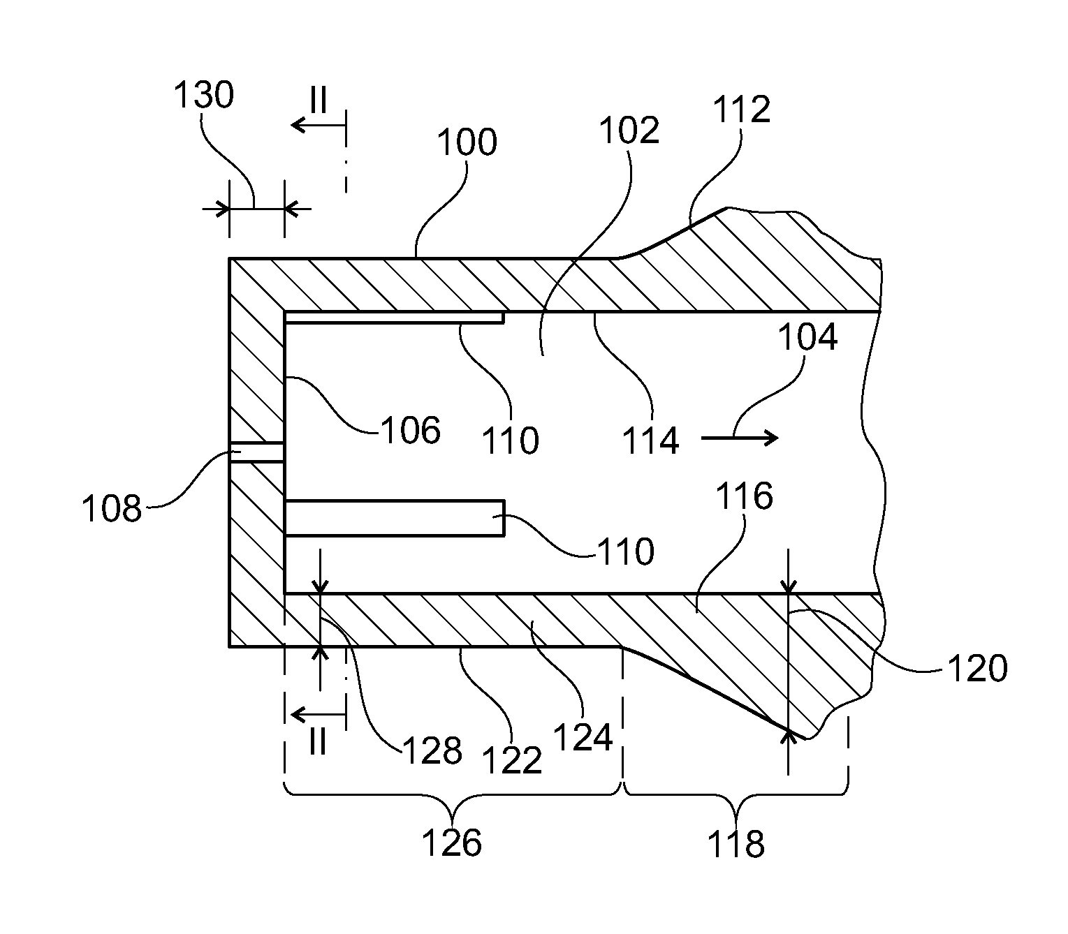
[0071]Referring now in greater detail to the drawings, FIG. 1 illustrates a sealing element according to embodiments of the herein disclosed subject matter.

[0072]The sealing element 100 is a structural element and is adapted for sealing a fluidic connection between a coupling element and a tubular element (not shown in FIG. 1). The sealing element 100 comprises a recess 102 extending in a longitudinal direction 104. The recess 102 is adapted for receiving a tubular element (not shown in FIG. 1). Further, the sealing element comprises a transverse wall defining an extent of the recess 102 in the longitudinal direction 104. The transverse wall 106 has a through hole 108.

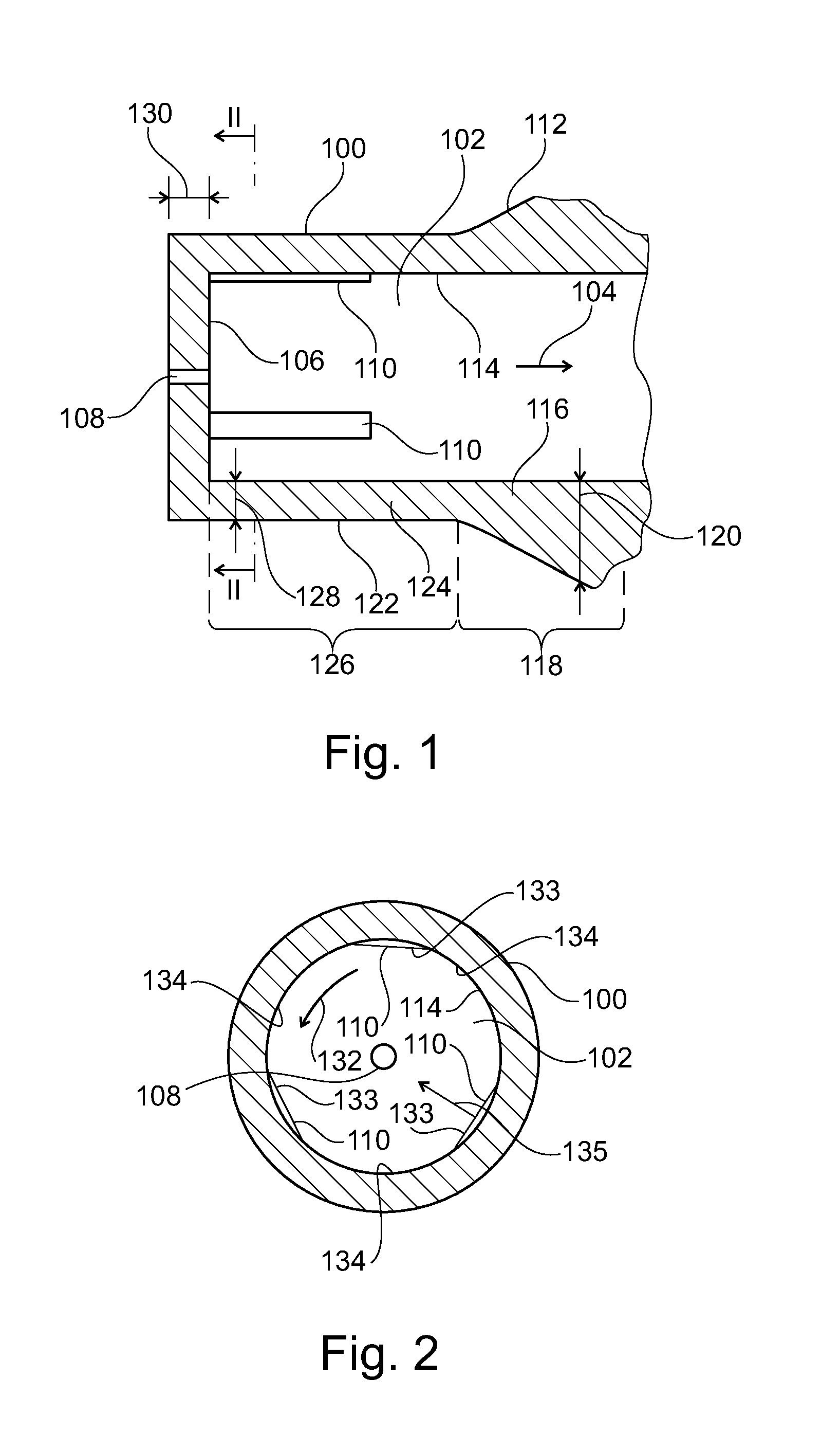
[0073]The sealing element 100 comprises, in accordance with an embodiment, three retaining elements 110, two of which are shown in FIG. 1. The retaining elements are adapted for retaining a tubular element in the recess 102. According to an embodiment, the retaining e...


PUM

PropertyMeasurementUnit
Pressureaaaaaaaaaa
Thicknessaaaaaaaaaa
Pressureaaaaaaaaaa

Abstract

A sealing element (100) for sealing a fluidic connection between a coupling element (258) and a tubular element (136) and thereby providing a sealed flow path through the tubular element (136) and between the coupling element (258) and the tubular element (136) in a longitudinal direction (104), the sealing element (100) comprising: a recess (102) extending in the longitudinal direction (104), the recess (102) being adapted for receiving the tubular element (136); a transverse wall (106) defining an extent of the recess (102) in the longitudinal direction (104), the transverse wall (106) having a through hole (108).

Description

BACKGROUND ART[0001]The present invention relates to a sealing element for a fluidic connection in a fluidic device, in particular in a high performance liquid chromatography application.[0002]In high performance liquid chromatography (HPLC), a liquid has to be provided usually at a very controlled flow rate (e.g. in the range of μl to ml / min) and a high pressure (typically 20 to 100 MPa, 200 to 1.000 bar and beyond up to currently 200 MPa, 2.000 bar) at which compressibility of the liquid becomes noticeable.[0003]For providing fluidic connections, tubular elements such as tubings are used. A typical tubular element used in a HPLC application is a glass capillary having an outer diameter of 1 millimeter or less.[0004]Sealingly coupling a tubular element with a coupling element may be a complex task, in particular if the diameter of the tubular element is small or if the tubular element comprises a brittle material. Moreover, the sealed connection of the tubular element with the coup...

Claims


Application Information

Patent Timeline
IPC IPC(8): F16L19/065F16L21/00G01N30/60F16J15/02
CPCG01N30/461G01N30/6026G01N30/6039Y10T29/49826Y10T29/49872F16J15/022F16L19/065F16L21/005G01N30/60G01N2030/027
Inventor REINHARDT, THOMASWAGNER, JOACHIM-RICHARD
Owner AGILENT TECH INC
Why Eureka
Try Eureka