Hybrid optical devices, and applications using same including optical cloaking system

a technology of optical devices and hybrid devices, applied in the direction of mirrors, instruments, mountings, etc., can solve the problems of difficult manufacture, transportation, handling, and difficult use of previously disclosed optical devices, and achieve the effect of reducing the overall length of the overall device, and reducing the depth or longitudinal dimension

Inactive Publication Date: 2015-08-20
LU WEIMIN
View PDF4 Cites 3 Cited by
  • Summary
  • Abstract
  • Description
  • Claims
  • Application Information

AI Technical Summary

Benefits of technology

[0010]Such hybrid optical device according to the first aspect is very advantageous and desirable over conventionally know optical devices for several reasons. For example, when the first portion corresponds to an aperture of the hybrid optical device, the sections of the first portion individually compress portions of the light entering the aperture, and then the sections of the second portion further compress the portions of the light so that the focal length of the overall device desirably becomes very short. This permits the incoming light to be significantly compressed or concentrated, and output in a predetermined direction, so that the hybrid optical devices of the invention have a significantly reduced depth or longitudinal dimension in comparison to conventionally known optical devices, even if the optical devices have an aperture with a relatively large height and/or width dimension though which incoming light enters the optical devices. Further, the optical devices can be constructed of ordinary, readily available materials with positive refractive index such as glass, transparent plastics including acrylic and polycarbonate, and even metals and other materials which can reflect light, while the optical device does not require any moving parts, power supply, or any type of signal reception or processing. Correspondingly, the optical device can be economically manuf...

Problems solved by technology

This creates practical limits for use of the previously disclosed optical devices because for ...

Method used


Image

  • Hybrid optical devices, and applications using same including optical cloaking system
  • Hybrid optical devices, and applications using same including optical cloaking system
  • Hybrid optical devices, and applications using same including optical cloaking system

Examples


Embodiment Construction

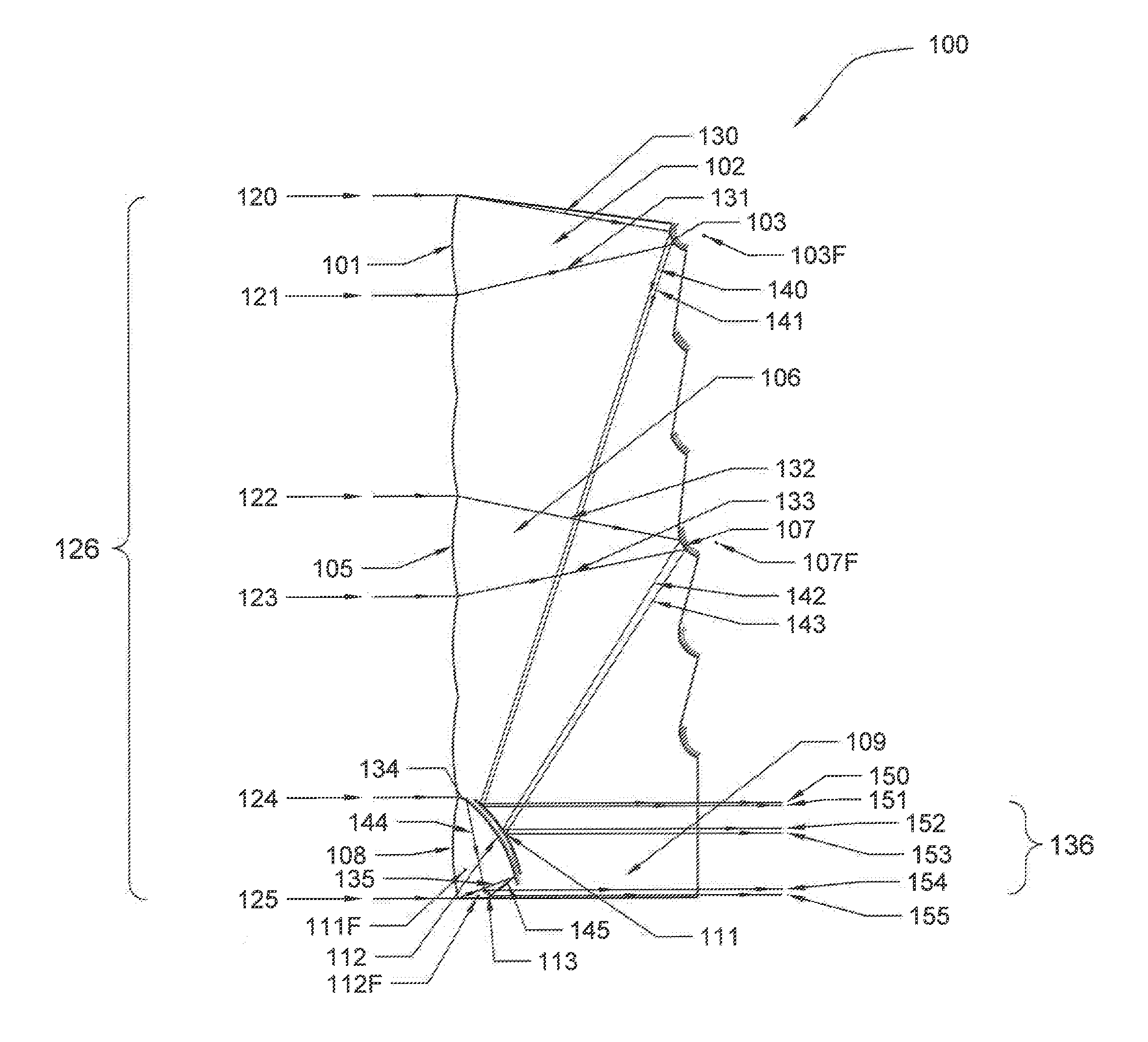
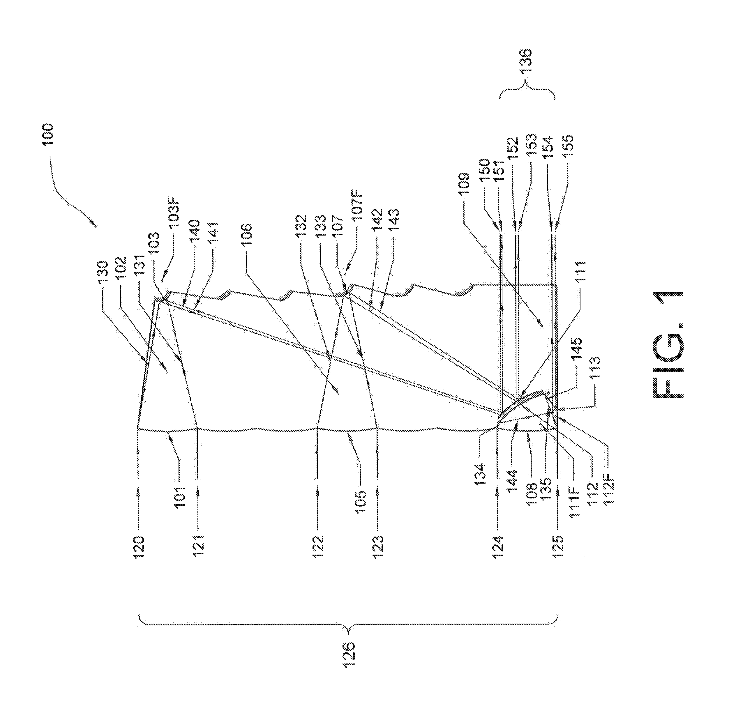
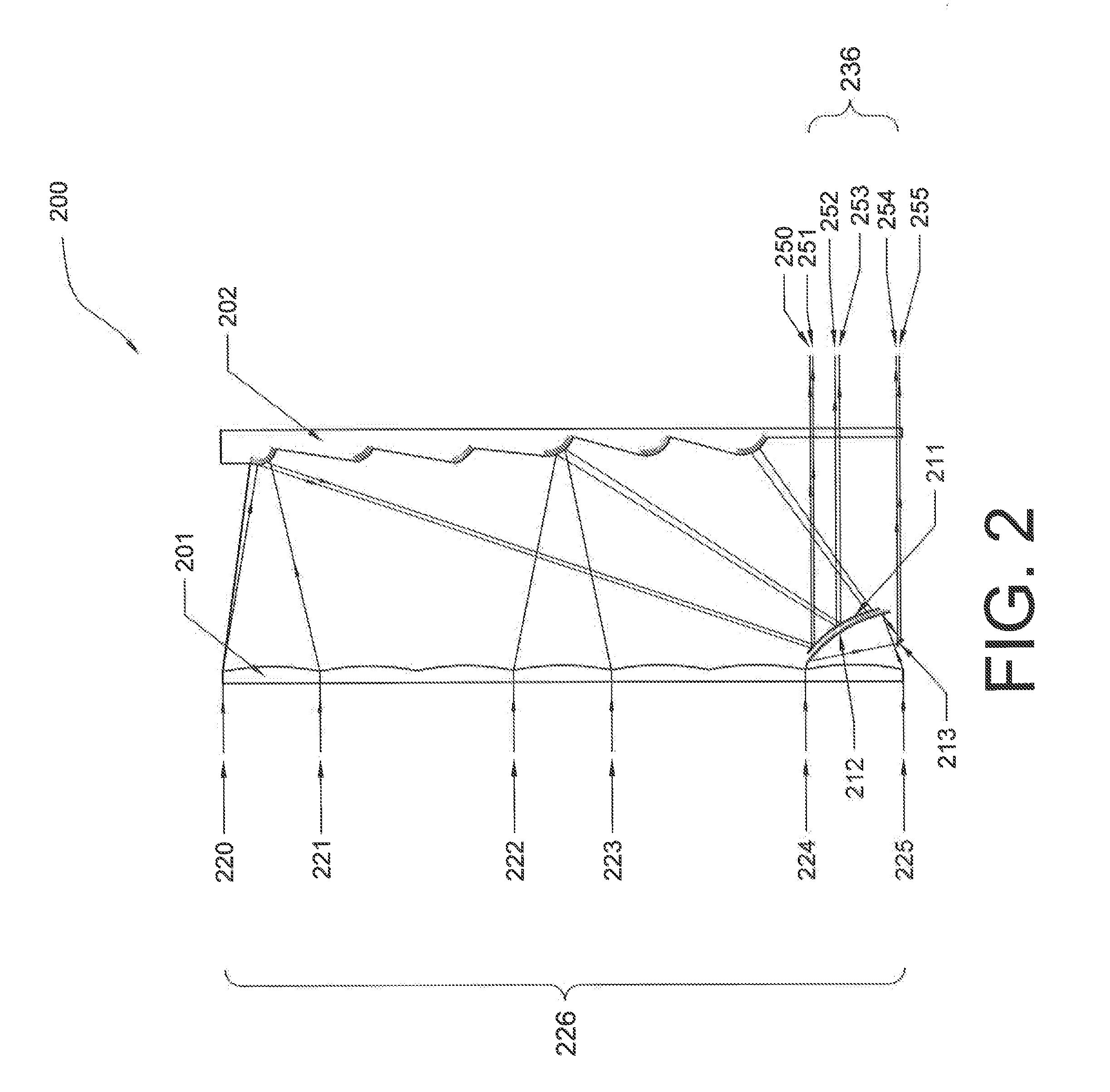
[0030]A number of selected illustrative embodiments of the invention will now be described in some detail, with reference to the drawings. It should be understood that only structures considered necessary for clarifying the present invention are described herein. Other conventional structures, and those of ancillary and auxiliary components of the system, are known and understood by those skilled in the art. These illustrative embodiments are hybrid optical devices and various applications of such devices.

[0031]Generally, a primary feature or aspect of all of the embodiments and applications of the hybrid optical devices according to the present invention is that they have very short focal lengths which is achieved by structurally dividing an aperture though which light enters the device into sections which then individually compress and redirect portions the light entering the aperture. The individually compressed and redirected portions of light may then be collected into one or a...


PUM


Abstract

A hybrid optical device for compressing light, including a first part which receives incident light shining on the device, wherein the first part is formed into sections along at least one direction thereof, wherein the sections receive respective portions of the light received by the first part, and individually compress and redirect the received portions of light, a second part which includes plural reflective surfaces which receive the compressed light from the sections of the first portion and further compress and redirect the portions of light, and a third part which receives the further compressed portions of light from the sections of the second part, and redirects same such that the light is output from the device.

Description

CROSS REFERENCE TO RELATED APPLICATIONS[0001]The present application is a continuation-in-part (CIP) of co-pending application Ser. No. 13 / 714,770 filed 14 Dec. 2012, which claims priority from U.S. Provisional Patent Application 61 / 646,570 filed 14 May 2012. The present application also claims priority from U.S. Provisional Patent Application 61 / 988,454 filed 5 May 2014 and U.S. Provisional Patent Application 62 / 089,356 filed 9 Dec. 2014. The entire disclosures of all of these prior applications are incorporated herein by reference.BACKGROUND OF THE INVENTION[0002]1. Field of the Invention[0003]The present invention relates to hybrid optical devices which significantly concentrate and change direction of light rays, and to various applications for such hybrid optical devices, including optical cloaking systems. More particularly, the present invention pertains to such hybrid optical devices which may be manufactured using commonly available materials, and which may have a very larg...

Claims


Application Information

Patent Timeline
IPC IPC(8): G02B5/10
CPCG02B5/10G02B5/09G02B17/008G02B17/02G02B17/08G02B17/086G02B27/0938
Inventor LU, WEIMIN
Owner LU WEIMIN
Why Eureka
Try Eureka