Perception Based Predictive Tracking for Head Mounted Displays

a head mounted display and predictive tracking technology, applied in the direction of instruments, optical elements, image enhancement, etc., can solve the problems of complex augmented reality systems, complex virtual reality environments, and crude virtual reality environments

Active Publication Date: 2015-08-20
META PLATFORMS TECH LLC
View PDF1 Cites 60 Cited by
  • Summary
  • Abstract
  • Description
  • Claims
  • Application Information

AI Technical Summary

Benefits of technology

The patent text describes a technology for predictive movement tracking in headmounted displays for virtual and augmented reality applications. The technology takes into account various factors such as jitter, latency, and overall responsiveness of the virtual reality system to improve the accuracy of predictive movement tracking. By dynamically applying motion prediction, the technology aims to reduce the problems associated with predictive movement tracking, such as overshooting and inaccuracy. The patent text also describes the use of perceptually tuned filtering to improve the quality of the virtual reality experience.

Problems solved by technology

These virtual reality environments maybe crude, either intentionally or through lack of capability of the virtual reality system.
However, virtual reality environments may also be detailed, interactive and quite complex, involving virtual people, conversations and experiences.
More complex augmented reality systems may superimpose “virtual” tangible objects onto a scene, such as walls, artwork, individuals and similar elements.
However, sample rates for the sensors identified above have typically been quite long—on the order tens of milliseconds—relative to the acuity of human vision.
Because the time between samples is long, these predictions often result in so-called “overshoot” where a prediction overshoots the actual head position and orientation or must be smoothed so severely to avoid other problems that they result in predictions sufficiently inaccurate that merely not predicting movement delivers better results.

Method used


Image

  • Perception Based Predictive Tracking for Head Mounted Displays
  • Perception Based Predictive Tracking for Head Mounted Displays
  • Perception Based Predictive Tracking for Head Mounted Displays

Examples


Embodiment Construction

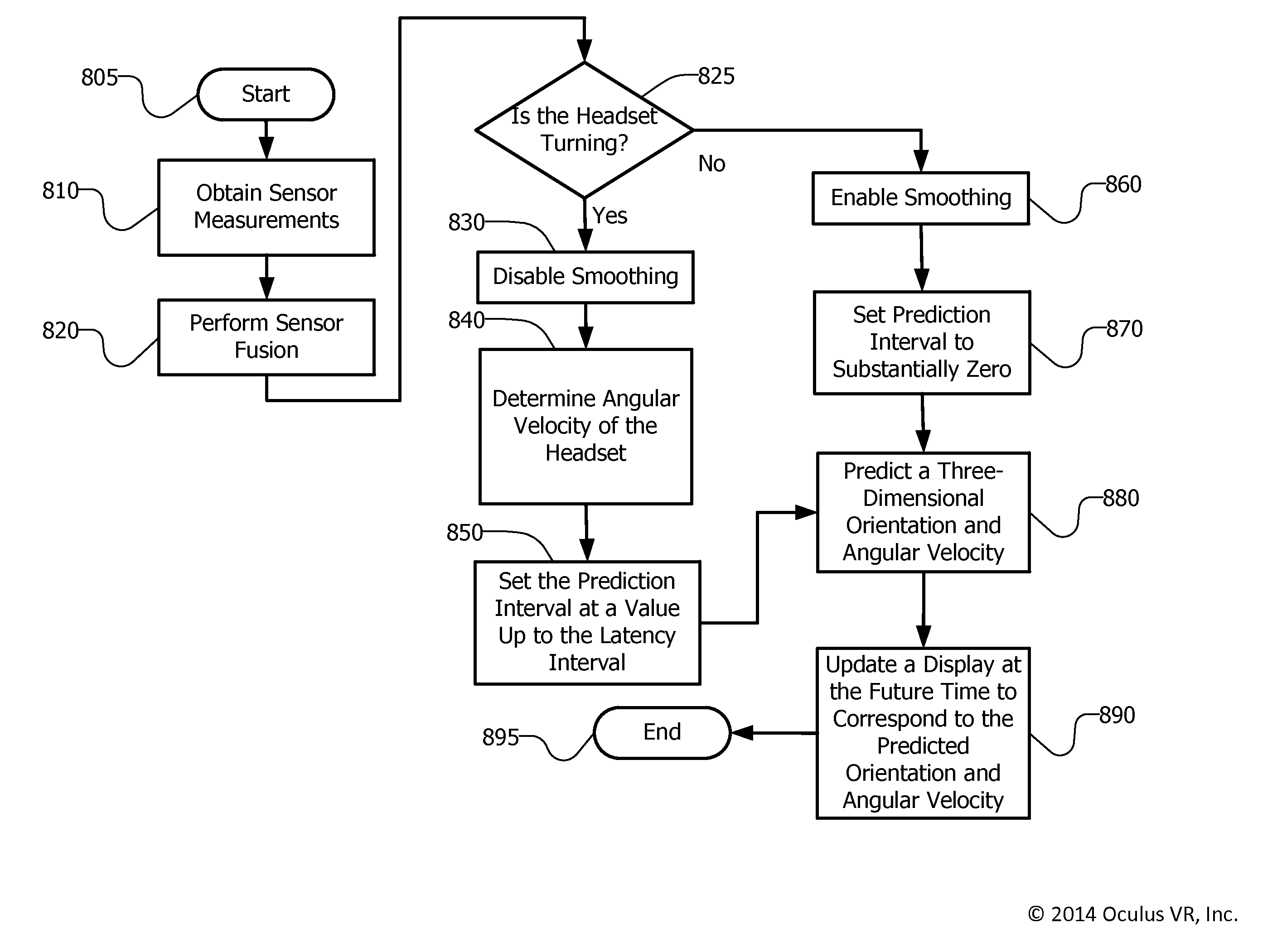
[0019]Dynamic application of motion prediction so as to take into account various factors including jitter, latency and overall responsiveness of the virtual reality system can significantly reduce the problems associated with predictive movement tracking. For example, only applying predictive movement to headsets that are moving and only to a degree suitable for the size of that movement provides better overall predictive accuracy than merely enabling predictive tracking for all movements and to the same degree (over the same prediction interval).

[0020]Similarly, smoothing, for example, regression-based averaging of recently detected movements may be applied much more aggressively when motion data indicates that a headset is substantially motionless, but much less aggressively when motion data indicates that a headset is moving at a relatively high angular velocity or is increasing in angular acceleration. This is because human eyes are very sensitive to so-called “jitter” when the...


PUM


Abstract

There is disclosed a method of and apparatus for predictive tracking for a head mounted display. The method comprises obtaining one or more three-dimensional angular velocity measurements from a sensor monitoring the head mounted display and setting a prediction interval based upon the one or more three-dimensional angular velocity measurements such that the prediction interval is substantially zero when the head mounted display is substantially stationary and the prediction interval increases up to a predetermined latency interval when the head mounted display is moving at an angular velocity of or above a predetermined threshold. The method further includes predicting a three-dimensional orientation for the head mounted display to create a predicted orientation at a time corresponding to the prediction interval, and generating a rendered image corresponding to the predicted orientation for presentation on the head mounted display.

Description

NOTICE OF COPYRIGHTS AND TRADE DRESS[0001]A portion of the disclosure of this patent document contains material which is subject to copyright protection. This patent document may show and / or describe matter which is or may become trade dress of the owner. The copyright and trade dress owner has no objection to the facsimile reproduction by anyone of the patent disclosure as it appears in the Patent and Trademark Office patent files or records, but otherwise reserves all copyright and trade dress rights whatsoever.RELATED APPLICATION INFORMATION[0002]This applications is a continuation of U.S. patent application Ser. No. 14 / 285,470, filed May 22, 2014, which claims the benefit and priority of U.S. Provisional Patent Application Ser. No. 61 / 829,008, filed May 30, 2013, all of which are hereby incorporated by reference.BACKGROUND[0003]1. Field[0004]This disclosure relates to predictive motion tracking for a head mounted display.[0005]2. Description of the Related Art[0006]Head mounted ...

Claims


Application Information

Patent Timeline
Patent Type & Authority Applications(United States)
IPC IPC(8): G06F3/01G02B27/01G02B27/00G06T5/00
CPCG02B27/0093G02B27/017G06F3/012G06T5/70G06T2207/20182
Inventor LAVALLE, STEVENGIOKARIS, PETER
Owner META PLATFORMS TECH LLC
Why Eureka
Try Eureka