Deadbolt-activated supplemental lock

Inactive Publication Date: 2015-09-10
AMESBURY GROUP
View PDF93 Cites 11 Cited by
  • Summary
  • Abstract
  • Description
  • Claims
  • Application Information

AI Technical Summary

Benefits of technology

This patent text discusses the use of locks on doors for security purposes. One type of lock is a latch, which can be actuated by a knob or thumb actuator to release the door. Another type is a deadbolt, which extends into the door frame to hold the door in place. Both of these types of locks can be used on hinged or sliding doors. However, the text explains that there is a risk of defeating these locks, particularly through a focus on the center of the door where the deadbolt is located. The technical effect of this patent is to provide a more secure and robust locking mechanism for doors, particularly with the use of deadbolts.

Problems solved by technology

Doors that utilize deadbolts may still be defeated, however, since it is generally well known by an intruder that the deadbolt is disposed proximate the center of the door, near the lock cylinder.
Thus, intruders often concentrate their breaching efforts against the center of the door to defeat the lock.

Method used


Image

  • Deadbolt-activated supplemental lock
  • Deadbolt-activated supplemental lock
  • Deadbolt-activated supplemental lock

Examples


Embodiment Construction

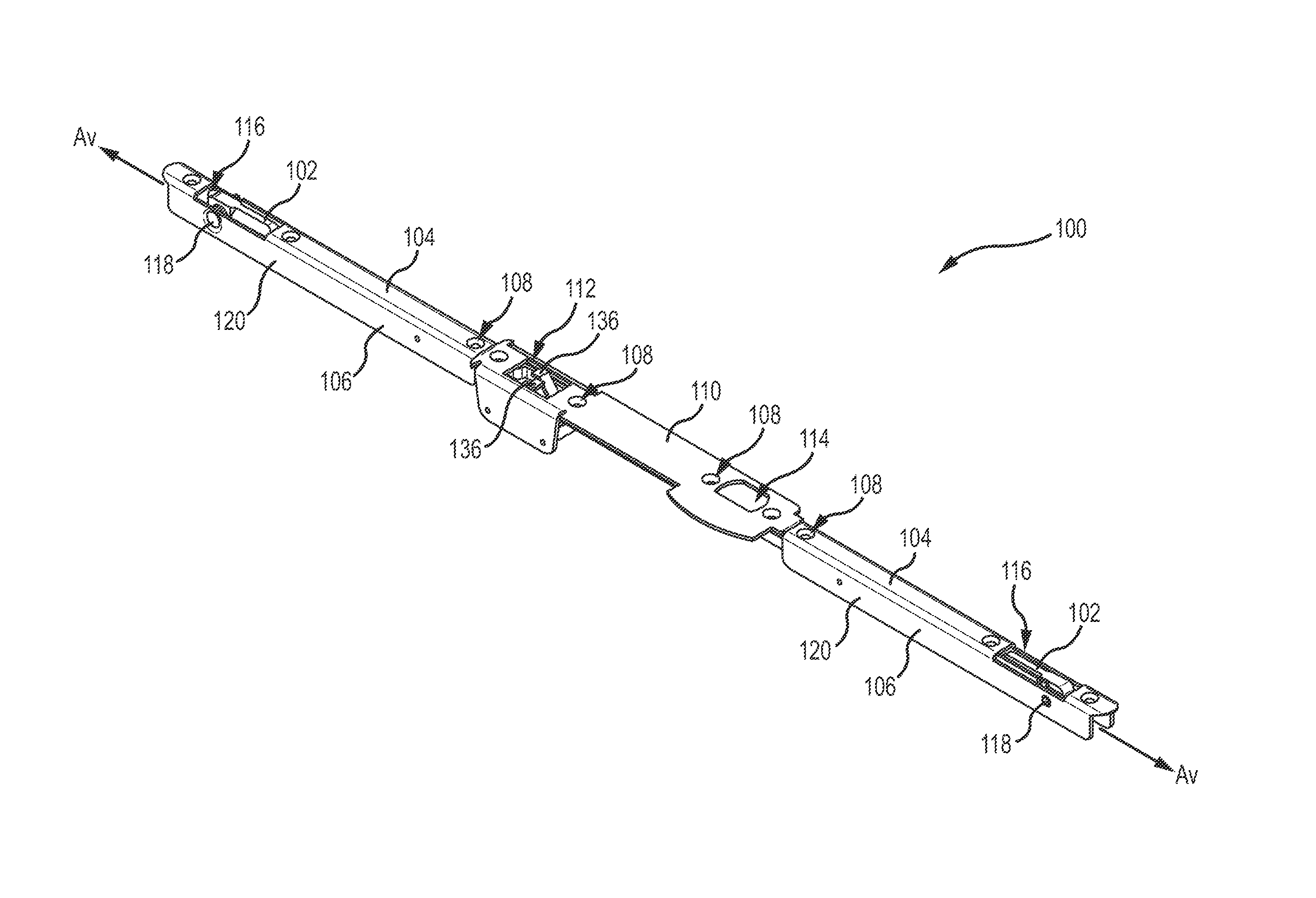
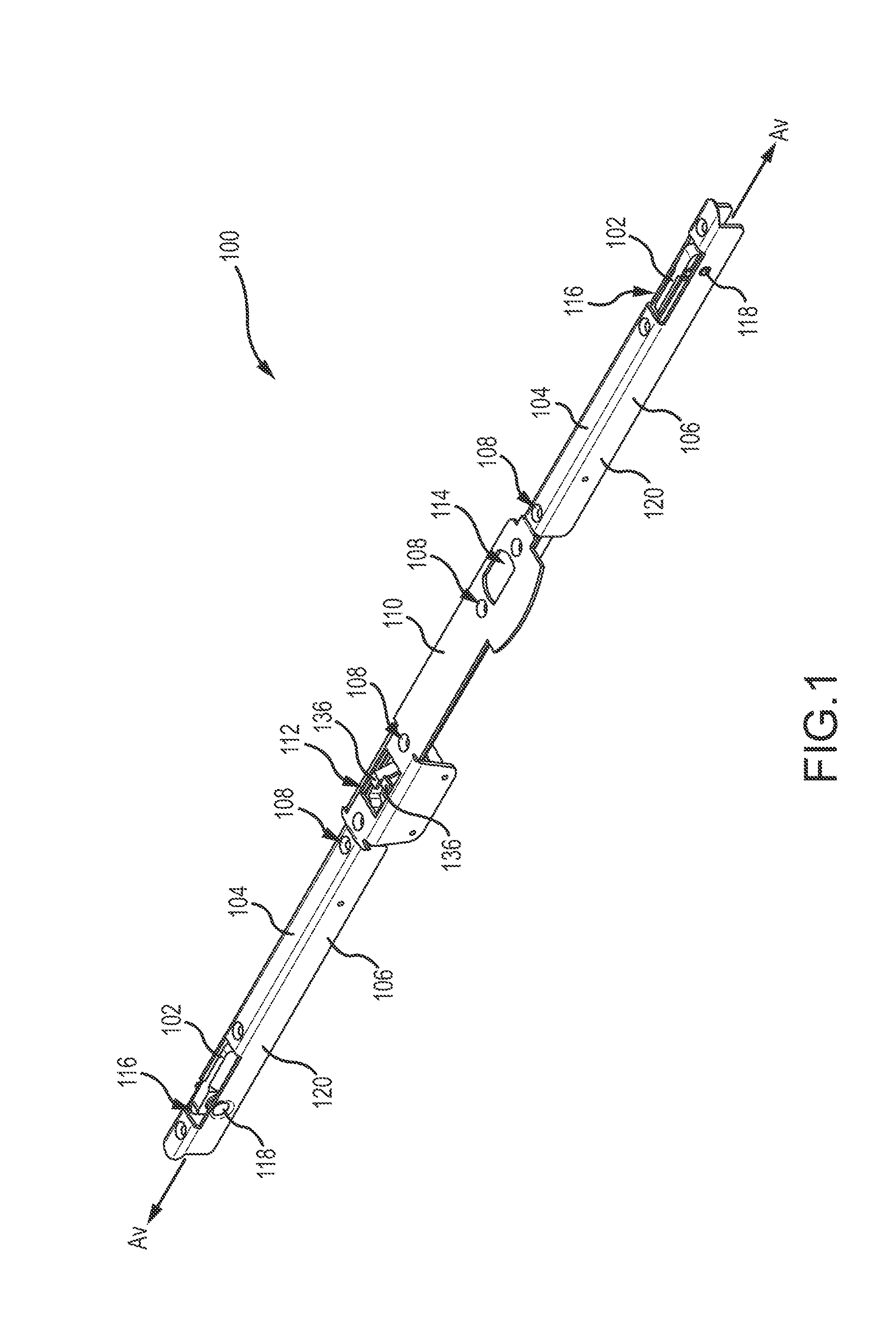
[0014]FIG. 1 depicts a perspective view of a deadbolt-activated supplemental lock 100. The multi-point lock 100 includes two spaced locking members 102. A base 104 of an elongate U-shaped channel 106 (described in more detail below in FIG. 2) is recessed into a door frame or a locking edge of an opposing door. For clarity, the lock 100 will be described as being installed in a door frame. A cover plate or face plate (not shown) may be secured to the base 104 through one or more screw holes 108 to cover the supplemental lock 100 for aesthetic purposes. The screw holes 108 can additionally be used with screws or other fasteners to secure the channel 106 to a door frame. The cover plate may also cover a centrally-disposed housing 110 that is connected to each of the two U-shaped channels 106. In another embodiment, the housing 110 and the U-shaped channels 106 define a unitary part. The screw holes 108 can additionally be used with screws to secure the channels 106 and housing 110 to t...


PUM


Abstract

A lock system has an elongate channel, a drive bar disposed within the housing, a locking element adapted to be actuated by the drive bar from a retracted position to an extended position; and a linkage connected to the drive bar. The linkage is adapted to be actuated from a first position to a second position by selective contact with a deadbolt disposed external to the elongate channel. Moving the linkage from the first position to the second position actuates the locking element from the retracted position to the extended position.

Description

CROSS-REFERENCE TO RELATED APPLICATIONS[0001]This application claims priority to and the benefit of U.S. Provisional Patent Application Ser. No. 61 / 947,602, filed Mar. 4, 2014, entitled, “Deadbolt-activated Supplemental Lock,” the disclosure of which is hereby incorporated by reference herein in its entirety.INTRODUCTION[0002]Locks are installed on hinged and sliding doors to lock the door within the frame for security purposes. Hinged doors, for example, typically include a locking latch. The latch holds the door closed but does not necessarily lock the door. The latch may be actuated by turning an associated door knob or by pressing a thumb actuator to release the latch. In certain doors, the latch may be locked to provide a degree of security. Doors (such as exterior doors) that include latches often include a deadbolt to provide enhanced security. The deadbolt extends into the door frame to hold the door in place. The deadbolt is actuated by a thumb turn on the interior of the d...

Claims


Application Information

Patent Timeline
IPC IPC(8): E05C1/02
CPCE05C1/02E05B63/242E05B65/0811E05C7/04E05C9/1875Y10T292/1014
Inventor HAGEMEYER, BRUCETAGTOW, GARY E.RAAP, DAN
Owner AMESBURY GROUP
Why Eureka
Try Eureka