Collapsible and stackable parts rack

Active Publication Date: 2015-09-17
HONDA LOGISTICS NORTH AMERICA
View PDF68 Cites 31 Cited by
  • Summary
  • Abstract
  • Description
  • Claims
  • Application Information

AI Technical Summary

Benefits of technology

[0011]It is another object of the invention to provide a rack with a retaining tab protruding from the leg member and a notch in the bearing bracket

Problems solved by technology

For example, some designs have utilized foldable opposing end frames that, while providing strength and stability, interfere with the rack surface when in a collapsed position.
This becomes a disadvantage in manufacturing situations wherein it is preferable for the rack surface of the topmost rack in a vertical stack to be freely accessible to assembly line workers or machines picking parts and components from the rack for utilization on the assembly line.
However, this is not desirable for situations in which quick and safe removal of the rack from an active area is needed, as is the case for assembly lines.
Disaggregate rack

Method used


Image

  • Collapsible and stackable parts rack
  • Collapsible and stackable parts rack
  • Collapsible and stackable parts rack

Examples


Embodiment Construction

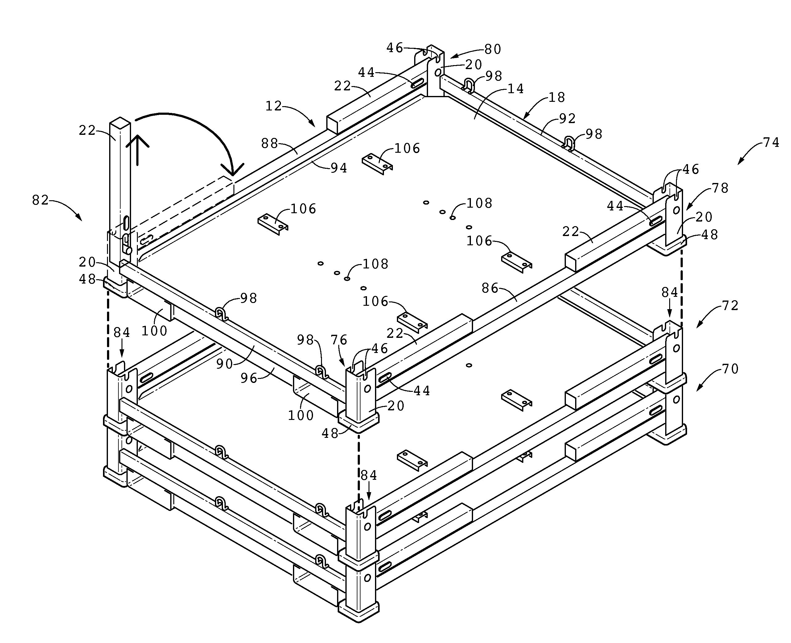
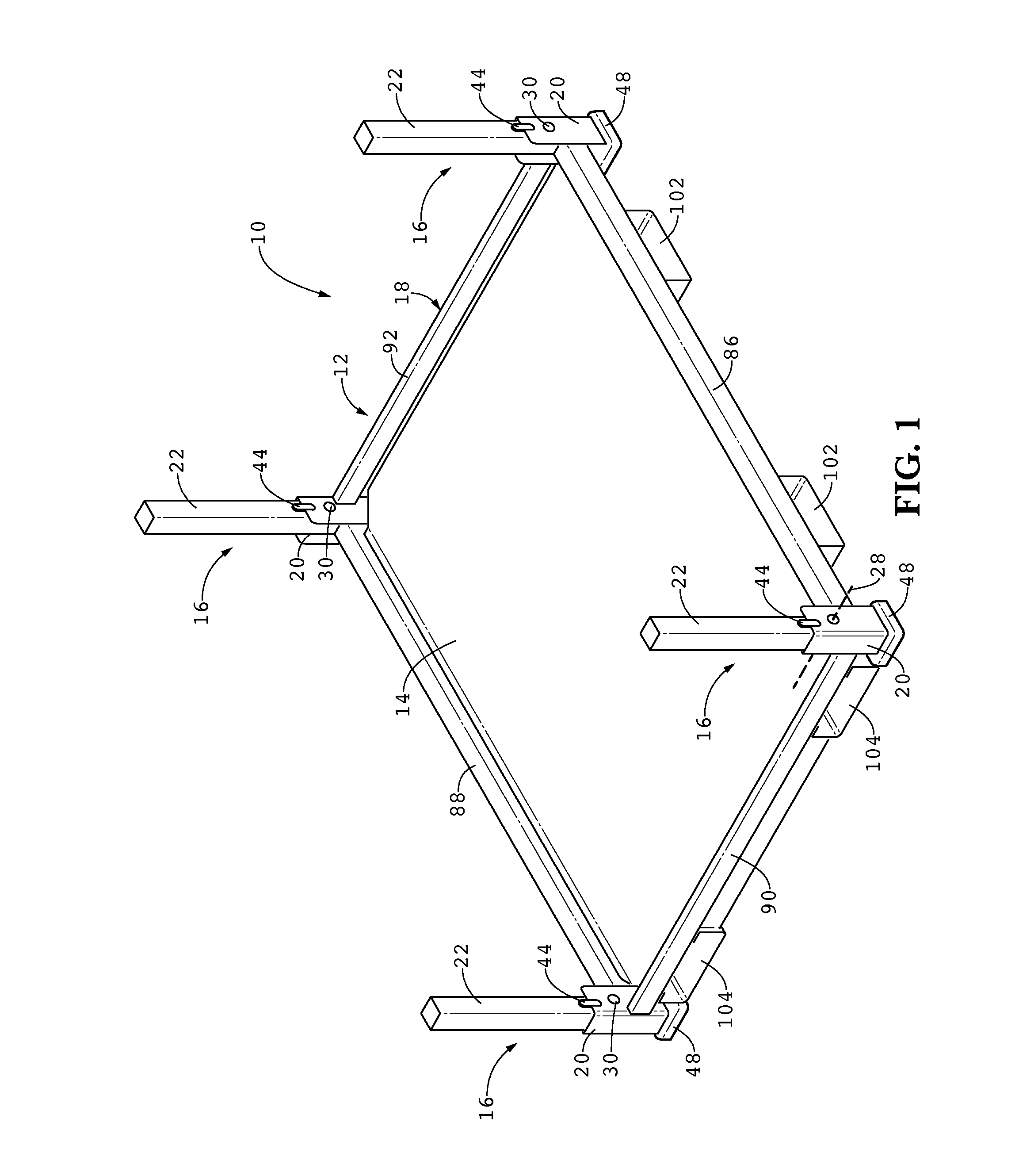
[0032]Exemplary embodiments of the present invention are directed to improved collapsible racks that are stackable whether in a collapsed or upright position, and being generally adapted for the purposes and advantages as set forth herein. One such exemplary embodiment of a rack 10 is shown in perspective view in an upright position in FIG. 1, in a side elevation view in FIG. 3, in a front elevation view in FIG. 4, in a top plan view in FIG. 5, and in a bottom plan view in FIG. 6. The rack 10 has a shelf 12 with a top surface 14 on which various articles or parts and components thereof (not shown) may be placed for storage, transport or the like. Preferably, the shelf 12 includes a single continuous top surface 14, but may also be provided as a series of slats, as a lattice structure, or other such discontinuous surface configurations. The shelf 12 depicted in the exemplary embodiment shown in FIG. 1 is substantially rectangular in shape, but can be any shape desired that is practic...


PUM

PropertyMeasurementUnit
Perimeteraaaaaaaaaa

Abstract

A rack for holding articles, components, parts and other such items and further being collapsible and stackable upon other similar racks whether any of the racks are in an upright or collapsed position. The rack includes a shelf and a plurality of leg assemblies distributed about the shelf perimeter, the leg assemblies each having a leg footer, a leg member, and a slider pivot bearing joining the proximal ends of the leg footer and leg member thereby constraining relative motion between the leg footer and leg member to two degrees of freedom. Embodiments of the rack further include retaining tabs on the leg member and corresponding notches on the leg footer to lock leg members in the upright position. Pairs of leg assemblies may be connected by primary connecting frame elements forming a portion of the perimeter, with the pairs being connected by secondary connecting frame elements forming another portion of the perimeter.

Description

CROSS-REFERENCE TO RELATED APPLICATIONS[0001]This application makes no priority claim.TECHNICAL FIELD[0002]Exemplary embodiments of the present invention relate generally to parts racks used with assembly lines, and more specifically to collapsible racks that are stackable whether in a collapsed or upright position.BACKGROUND OF THE INVENTION[0003]Many forms of racks, stands, shelves and other such support structures, hereinafter referred to simply as “racks,” have been used for holding articles. Portable racks are used in manufacturing environments to deliver parts to an assembly line for inclusion in or preparation for inclusion in a manufacturing product. Racks are also used to provide uniform storage for articles, parts or components, and further in situations in which transportation and delivery of such items is needed.[0004]Racks are numerous in design, and attempts to improve upon them have been made in the past to suit a variety of needs. One general improvement has been to ...

Claims


Application Information

Patent Timeline
IPC IPC(8): A47B47/00A47B57/32A47B55/00
CPCA47B47/0091A47B47/0025A47B57/32A47B55/00A47B47/005A47B47/021A47B47/03A47B87/0253A47B87/02A47B47/00A47B43/00
Inventor NAKA, MASAAKIMAEDA, NOBUHIRO
Owner HONDA LOGISTICS NORTH AMERICA
Why Eureka
Try Eureka