Connector, wireless communication module, wireless communication device, and electronic apparatus

a wireless communication module and wireless communication technology, applied in the direction of coupling device connection, resonant antenna, instruments, etc., can solve the problems of reduced reception sensitivity and increased costs, and achieve good communication conditions

Active Publication Date: 2015-09-24
SEIKO EPSON CORP
View PDF2 Cites 1 Cited by
  • Summary
  • Abstract
  • Description
  • Claims
  • Application Information

AI Technical Summary

Benefits of technology

[0037]According to the aspects of the invention, it is possible to achieve good communication conditions, regardless of the installation position.

Problems solved by technology

In communication using radio waves with high directivity, there is a problem that reception sensitivity is reduced according to the installation position of a communication device.
In JP-A-2013-117660, a mechanism for adjusting the direction of the receiving device is needed, which results in an increase in costs.

Method used


Image

  • Connector, wireless communication module, wireless communication device, and electronic apparatus
  • Connector, wireless communication module, wireless communication device, and electronic apparatus
  • Connector, wireless communication module, wireless communication device, and electronic apparatus

Examples


Embodiment Construction

[0047]Hereinafter, an embodiment of the invention will be described with reference to the accompanying drawings.

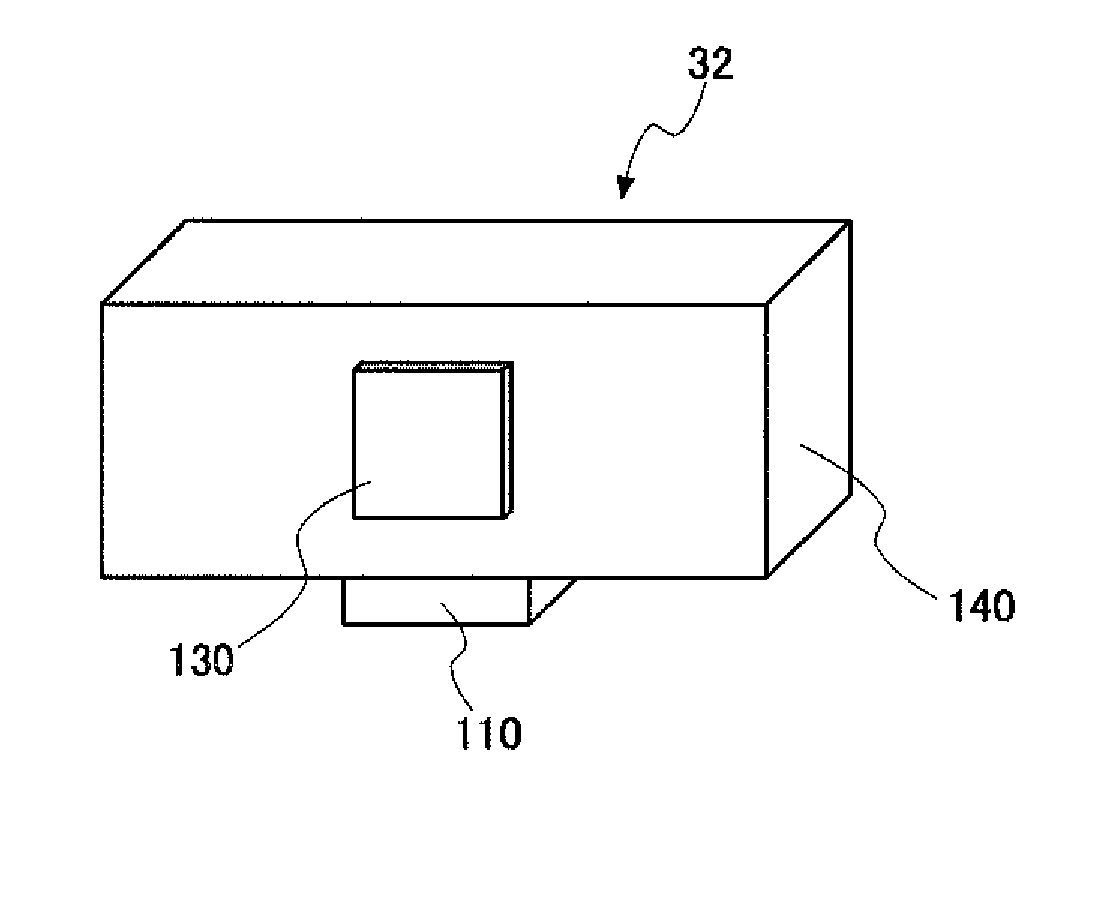
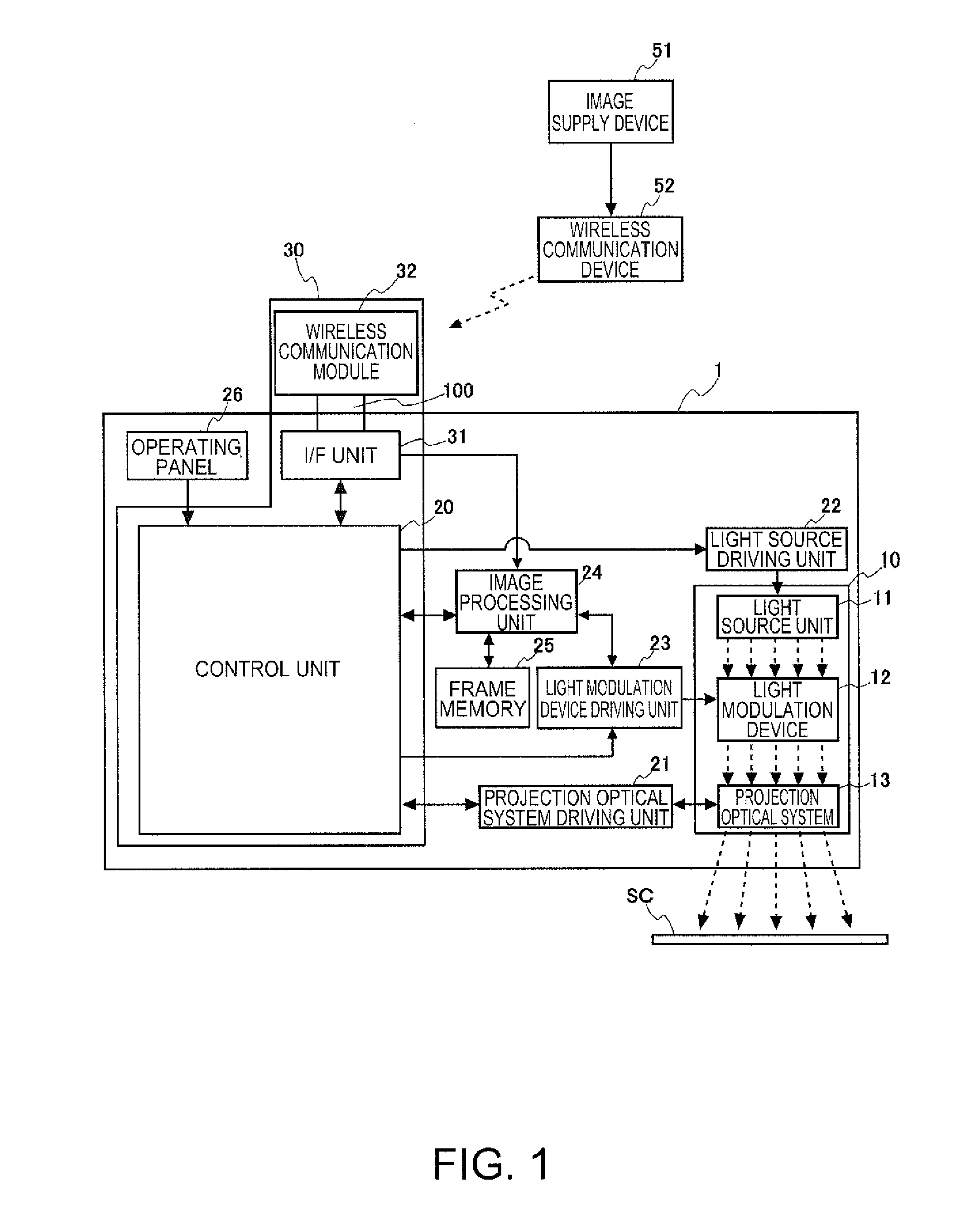
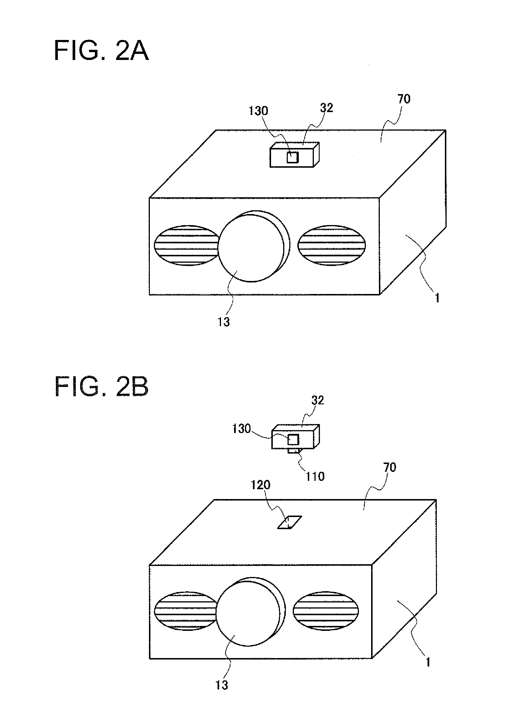
[0048]First, the structure of this embodiment will be described with reference to FIG. 1. In this embodiment, a projector 1 and an image supply device 51 are connected to each other by wireless communication. A wireless communication module 32 connected to the projector 1 and a wireless communication device 52 connected to the image supply device 51 perform wireless communication therebetween such that image data supplied from the image supply device 51 is transmitted to the projector 1. The projector 1 projects and displays an image based on the image data received from the image supply device 51 on a screen SC. Examples of the image supply device 51 include a video reproduction device, a digital versatile disk (DVD) reproduction device, a television tuner device, a cable television (CATV) set-top box, a video output device of a video game machine, and a personal computer...


PUM


Abstract

A connector includes a plug and a receptacle which are fitted to each other and is used to connect a wireless communication module to an electronic apparatus. The plug includes a plurality of contacts. When the plug is connected to the receptacle in any of the first and second directions which are symmetric with respect to the center of a junction surface with the receptacle, the plurality of contacts are connected to contacts of the receptacle.

Description

[0001]The entire disclosure of Japanese Patent Application No. 2014-057683, filed Mar. 20, 2014, is expressly incorporated by reference herein.BACKGROUND[0002]1. Technical Field[0003]The present invention relates to a connector, a wireless communication module, a wireless communication device, and an electronic apparatus.[0004]2. Related Art[0005]In communication using radio waves with high directivity, there is a problem that reception sensitivity is reduced according to the installation position of a communication device. JP-A-2013-117660 discloses a technique in which a driving unit that changes the direction of a receiving device for wirelessly receiving image information is provided to change the direction of the receiving device on the basis of reception sensitivity.[0006]In JP-A-2013-117660, a mechanism for adjusting the direction of the receiving device is needed, which results in an increase in costs.SUMMARY[0007]An advantage of some aspects of the invention is to provide a...

Claims


Application Information

Patent Timeline
Patent Type & Authority Applications(United States)
IPC IPC(8): H01R24/28H01Q1/46H01R24/76
CPCH01R24/28H01Q1/46H01R24/76H01Q21/28G03B21/14G03B2206/00H01Q9/0407H01R24/86H01R2107/00H04N9/3141H04W4/80
Inventor NAGUMO, TAKASHIHASHIMOTO, HIROYUKI
Owner SEIKO EPSON CORP
Why Eureka
Try Eureka