
Mobile communications network, methods, base station, relay node and communications terminal

a mobile communication network and relay node technology, applied in the field of mobile communications networks, methods, base stations, relay nodes and communications terminals, can solve the problems of relay synchronisation signals not providing any way of a priori, not providing information on any other parts of the radio channel, and the radio channel between the communications terminal and the relay node or the relay node may be very wide, so as to reduce the number of failed transmissions, improve the overall latency of the d2d connection, and reduce the number of failed transmission

Active Publication Date: 2019-10-08
SONY CORP
View PDF32 Cites 0 Cited by
  • Summary
  • Abstract
  • Description
  • Claims
  • Application Information

AI Technical Summary

Benefits of technology

[0012]A problem arising from an application of device to device (D2D) communications is that a radio channel between a communications terminal and a relay node or between relay nodes may be very wide. It would be preferable for the transmitting relay node to transmit signals in a part of the radio channel that has best radio communications conditions with respect to possible fading. Relay synchronisation signals may only cover a middle part of the radio channel, and do not provide any channel state information over other parts of the radio channel. When signals representing data packets are sent between D2D communications channels, demodulation reference symbols assist in channel estimation and demodulation of the signals to detect the data packet, but they do not provide information on any other parts of the radio channel. Relay synchronisation signals do not provide any way of a priori establishment of the channel state for scheduling purposes, which is achieved for LTE uplink transmissions by communications terminals transmitting sounding reference symbols (SRS).
[0013]Accordingly, the present disclosure can provide an arrangement for implementing channel sounding in D2D communications between two communicating terminals. The present disclosure makes it possible for D2D devices to send transport blocks in D2D resources that have good channel state characteristics. Scheduling transmissions to frequency resources with a better channel state reduces the number of failed transmissions, retransmissions (if used) and thus improves overall latency across the D2D connections.

Problems solved by technology

A problem arising from an application of device to device (D2D) communications is that a radio channel between a communications terminal and a relay node or between relay nodes may be very wide.
Relay synchronisation signals may only cover a middle part of the radio channel, and do not provide any channel state information over other parts of the radio channel.
When signals representing data packets are sent between D2D communications channels, demodulation reference symbols assist in channel estimation and demodulation of the signals to detect the data packet, but they do not provide information on any other parts of the radio channel.
Relay synchronisation signals do not provide any way of a priori establishment of the channel state for scheduling purposes, which is achieved for LTE uplink transmissions by communications terminals transmitting sounding reference symbols (SRS).

Method used


Image

  • Mobile communications network, methods, base station, relay node and communications terminal
  • Mobile communications network, methods, base station, relay node and communications terminal
  • Mobile communications network, methods, base station, relay node and communications terminal

Examples


Embodiment Construction

[0028]Hereinafter preferred embodiments of the present technique will be described in detail with reference to the appended drawings. Note that, in this specification and appended drawings, structural elements that have substantially the same function and structure are denoted with the same reference numerals, and repeated explanation of these structural elements is omitted.

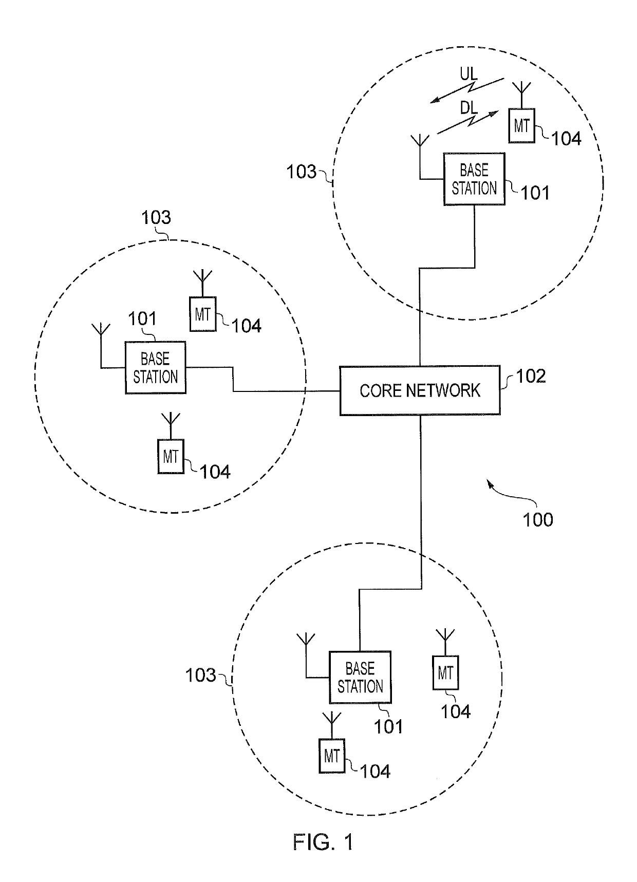
[0029]FIG. 1 provides a schematic diagram illustrating some basic functionality of a conventional mobile telecommunications network, using for example a 3GPP defined UMTS and / or Long Term Evolution (LTE) architecture. The mobile telecommunications network / system 100 of FIG. 1 operates in accordance with LTE principles and which may be adapted to implement embodiments of the disclosure as described further below. Various elements of FIG. 1 and their respective modes of operation are well-known and defined in the relevant standards administered by the 3GPP® body, and also described in many books on the subject, for...


PUM


Abstract

A base station receives measurement information from infrastructure units, and this measurement information in order to create a look-up table. Based on analysis of the measurement information, an indication of connections between a relay node and communications terminals in the network is transmitted, and communications resources are assigned to each of the infrastructure units in the network. The relay node in the network transmits channel sounding signals to be measured by other infrastructure units, in their assigned communications resource, and with a specified transmission power. The infrastructure units which detect the channel sounding signals can then use them to measure and estimate a state of the channel and determine which frequency resources to use when scheduling transmissions.

Description

CROSS-REFERENCE TO RELATED APPLICATIONS[0001]The present application claims priority to European Patent Application 15162010.1, filed in the European Patent Office on Mar. 31, 2015, the entire contents of which are incorporated herein by reference.TECHNICAL FIELD OF THE DISCLOSURE[0002]The present disclosure relates to mobile communications networks, methods, base stations, relay nodes and communications terminals, and more specifically to providing an arrangement in which one or more relay nodes transmit channel sounding signals in assigned communications resources in order to measure a channel quality across a frequency spectrum between the relay nodes and communications terminals.[0003]Embodiments of the present technique can provide methods of communicating data in a small cell environment where relay nodes may be used.BACKGROUND OF THE DISCLOSURE[0004]The “background” description provided herein is for the purpose of generally presenting the context of the disclosure. Work of t...

Claims


Application Information

Patent Timeline
Patent Type & Authority Patents(United States)
IPC IPC(8): H04W72/08H04B7/155H04W16/26H04W84/04H04W72/04
CPCH04W72/085H04B7/155H04B7/15528H04W72/0446H04W16/26H04W84/047H04W72/0473H04W72/542
Inventor KAHTAVA, JUSSI TAPANIWAKABAYASHI, HIDEJI
Owner SONY CORP
Learn More