
Integrated motor and pump assembly

a technology of integrated motors and components, applied in machines/engines, liquid fuel engines, positive displacement liquid engines, etc., can solve the problems of increasing the size, weight and cost of the pump(s), limiting flexibility and control over the collective pumping system when multiple pumps

Inactive Publication Date: 2015-10-01
SCHLUMBERGER TECH CORP
View PDF7 Cites 147 Cited by
  • Summary
  • Abstract
  • Description
  • Claims
  • Application Information

AI Technical Summary

Benefits of technology

This patent introduces an apparatus for moving fluids using a pump assembly with rods, reciprocating members, and an electric motor. The motor rotates the crankshaft, which causes the rods to move the recipcing members, resulting in the fluid being moved. The technical effect of this invention is an efficient and effective apparatus for pumping fluids.

Problems solved by technology

However, due to their size and / or weight, a limited number of pumps may be mounted on a single truck or skid.
This also increases the size, weight, and cost of the pump(s).
Moreover, each engine is individually fueled and controlled, which limits flexibility and control over a collective pumping system when multiple pumps are being operated simultaneously.

Method used


Image

  • Integrated motor and pump assembly
  • Integrated motor and pump assembly
  • Integrated motor and pump assembly

Examples


Embodiment Construction

[0020]It is to be understood that the following disclosure provides many different embodiments, or examples, for implementing different features of various embodiments. Specific examples of components and arrangements are described below to simplify the present disclosure. These are, of course, merely examples and are not intended to be limiting. In addition, the present disclosure may repeat reference numerals and / or letters in the various examples. This repetition is for simplicity and clarity, and does not in itself dictate a relationship between the various embodiments and / or configurations discussed. Moreover, the formation of a first feature over or on a second feature in the description that follows may include embodiments in which the first and second features are formed in direct contact, and may also include embodiments in which additional features may be formed interposing the first and second features, such that the first and second features may not be in direct contact....


PUM


Abstract

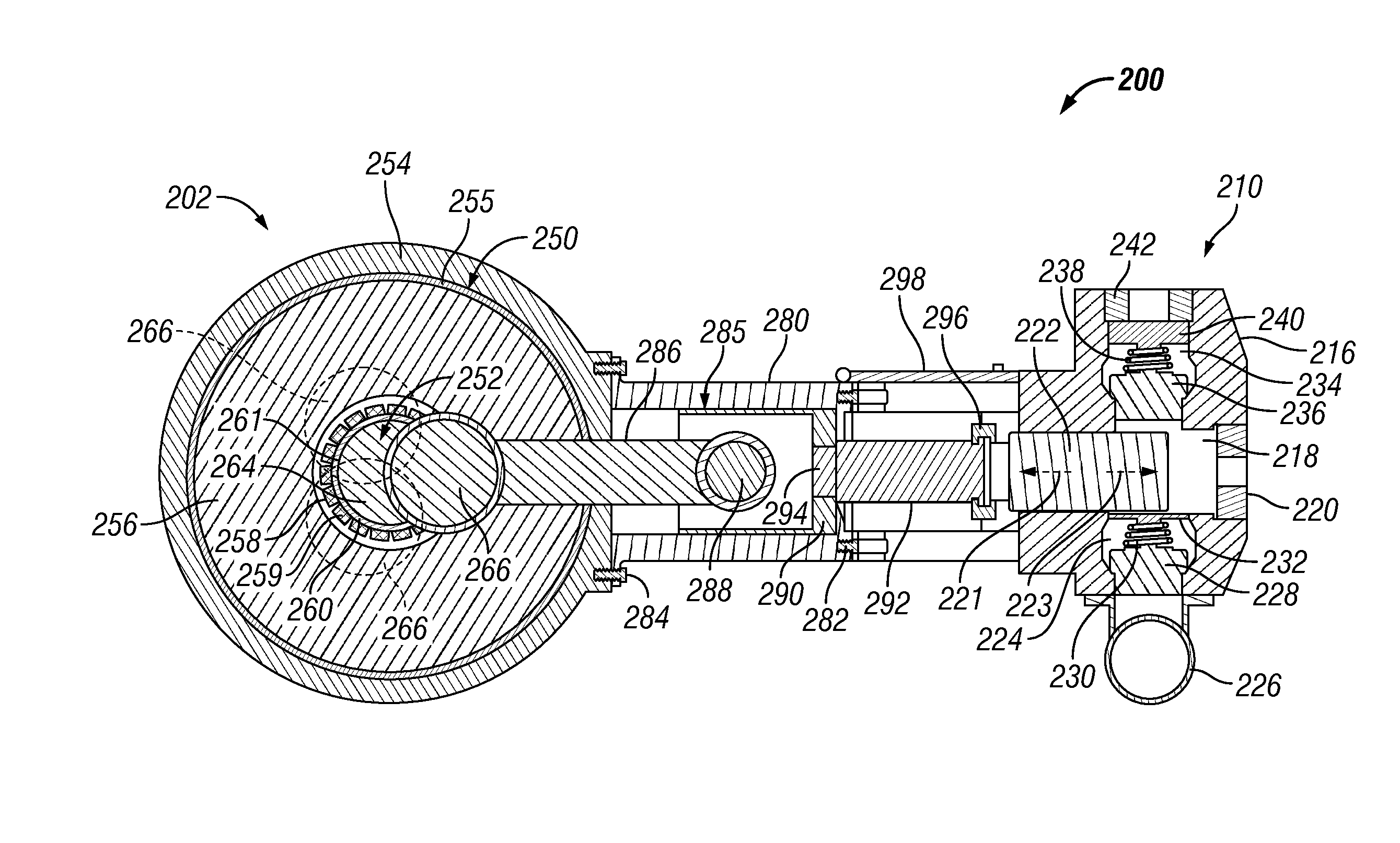
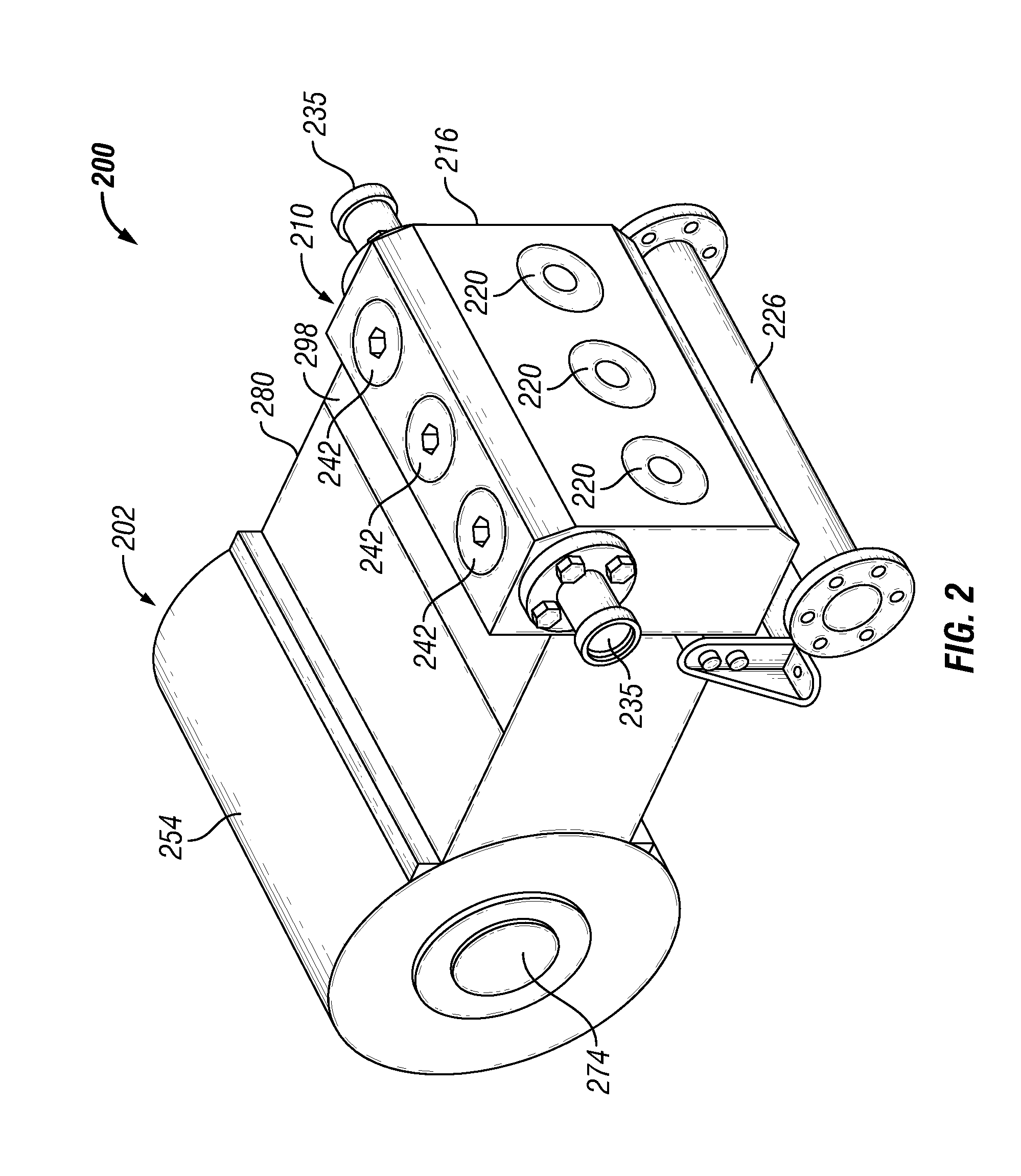
A pump assembly that includes a crankshaft having main journals and crankpin journals, rods operatively coupled with the crankpin journals, reciprocating members operatively coupled with the rods, and an electric motor operable to rotate the crankshaft. The electric motor includes a stator and a rotor. The rotor is directly connected with the crankshaft and is operable to rotate the crankshaft to move the plurality of rods and reciprocating members to move a fluid.

Description

CROSS-REFERENCE TO RELATED APPLICATIONS[0001]This application claims priority to and the benefit of U.S. Provisional Application No. 61 / 973,065 entitled “Integrated Electric Motor Power-end for Reciprocating Pumps,” filed Mar. 31, 2014, the entire disclosure of which is hereby incorporated herein by reference.Background of the Disclosure[0002]In oilfield operations, reciprocating pumps are utilized at wellsites for large scale, high-pressure operations. Such operations may include drilling, cementing, acidizing, water jet cutting, and hydraulic fracturing of subterranean formations. In some applications, several pumps may be connected in parallel to a single manifold, flow line, or well. Some reciprocating pumps include reciprocating members driven by a crankshaft toward and away from a fluid chamber to alternatingly draw in, pressurize, and expel fluid from the fluid chamber. Hydraulic fracturing of a subterranean formation, for example, may utilize fluid at a pressure exceeding 10...

Claims


Application Information

Patent Timeline
IPC IPC(8): F04B53/00F04B53/14F04B17/03F04B1/12F04B1/14
CPCF04B53/006F04B1/128F04B53/144F04B17/03F04B1/148F04B1/0404F04B53/147
Inventor CHONG, JONATHAN WUN SHIUNG
Owner SCHLUMBERGER TECH CORP
Learn More