Stop valve for coffee maker
a technology for coffee makers and stop valves, applied in the field of kitchen appliances, can solve the problems of large and high-power heaters, inconvenient operation, and inability to meet the needs of large-scale heating, and achieve the effect of variable brewing temperature and level of coffee extraction
Inactive Publication Date: 2015-10-08
LEVINE HARVEY +1
View PDF4 Cites 13 Cited by
- Summary
- Abstract
- Description
- Claims
- Application Information
AI Technical Summary
Benefits of technology
[0025]Using a stop valve with a lightweight ball piston, as is currently done in essentially all production-level automatic drip coffee makers, results in signific
Problems solved by technology
Coffee extracted using lower temperature water is, all things being equal, usually inferior.
The performance of conventional drip coffee makers is generally faulted because they take a long time to raise the temperature of the water delivered to the grounds to the optimal range.
This problem is especially pronounced with smaller coffee makers, such as those yielding five cups or less, because the input wattage and the total time available to heat the system and brew the coffee are less than with full-size machines.
Higher powered and larger heating elements are one method of
Method used
View moreImage
Smart ImageViewing Examples
Examples
 PUM
 Abstract
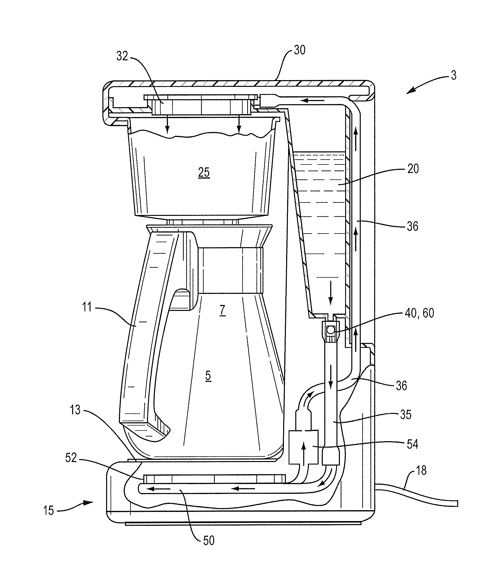
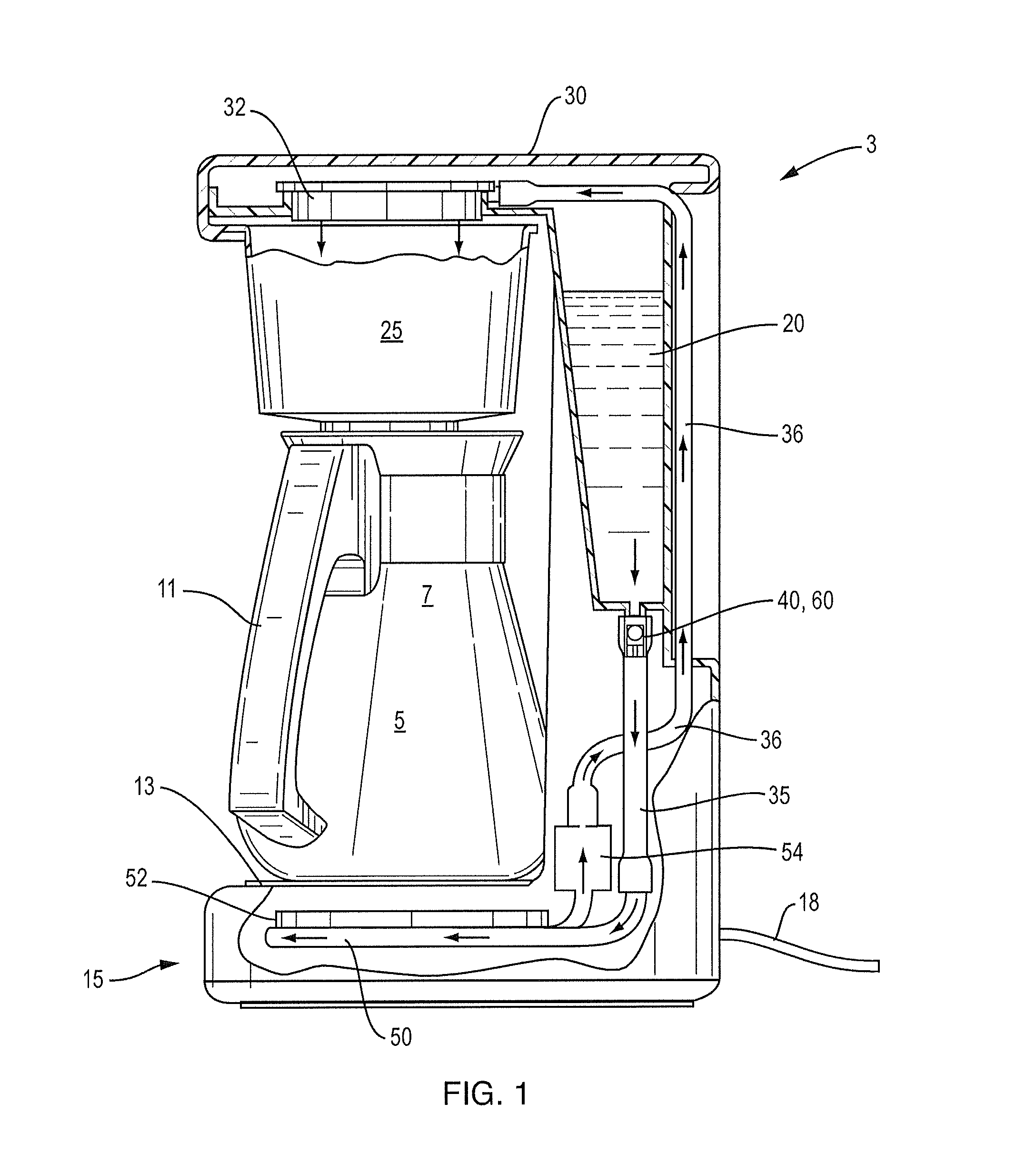
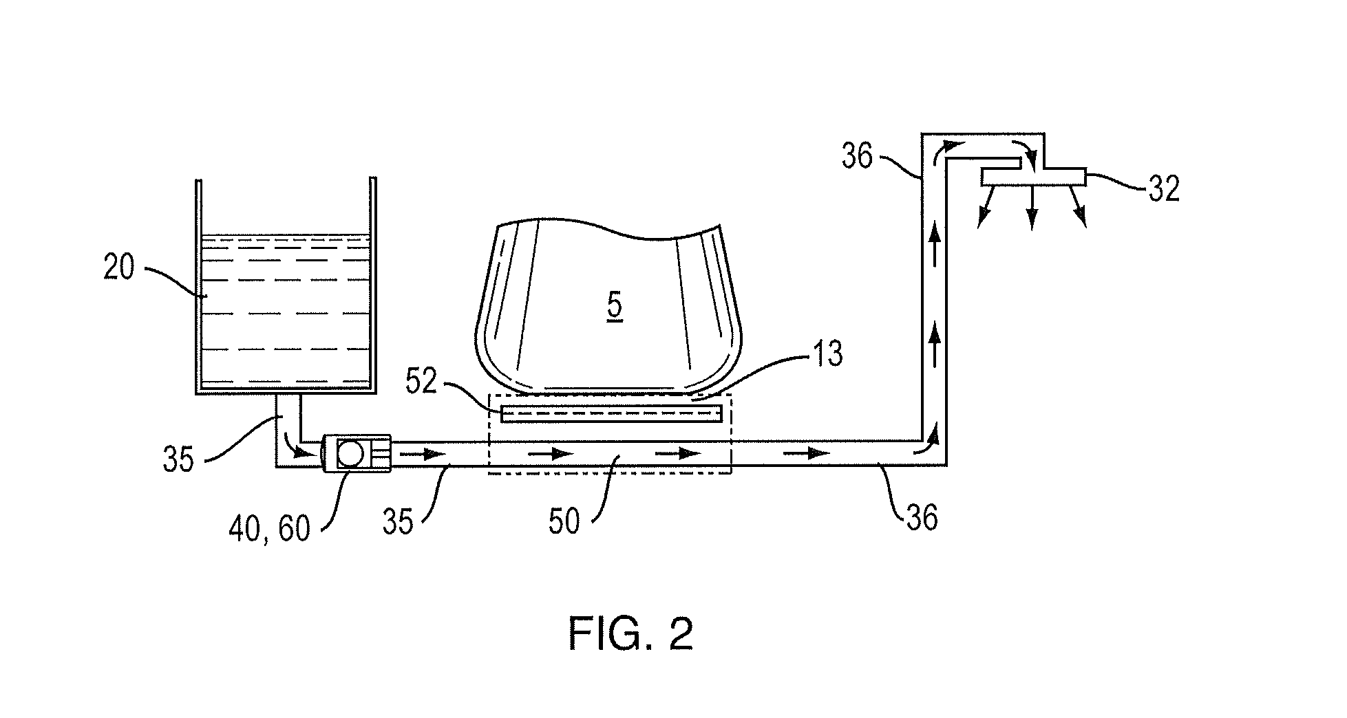
Drip coffee makers include a one way valve to control a flow of fresh water from a reservoir into a heating conduit via a cold water conduit. Water is heated in the heating conduit, and then proceeds into a hot water conduit, and hot water is thereafter spread over coffee grounds by a showerhead. Heating water causes formation of steam and pressure in the hot water conduit. The one way valve prevents the heated water from moving backwards towards the reservoir, helping force the water onward through the system towards the coffee grounds in the filter basket. Once the heated steam and water move out of the heating conduit the one-way valve is able to open and new fresh water enters. The one-way valves use heavy metal or steel valve stoppers. The stoppers may be spherical, columnar, bullet shaped, or a pair of spheres either loose or fused.
Description
RELATED APPLICATION[0001]This application claims the benefit of U.S. Provisional Patent Application No. 61 / 725,554, filed Nov. 13, 2012, which is fully incorporated by reference herein.FIELD AND BACKGROUND OF THE INVENTION[0002]The present invention relates generally to the field of kitchen appliances, and in particular to drip coffee makers, and to valves for controlling water flow through coffee makers.[0003]Drip brewing coffee involves pouring water over roasted, ground coffee beans contained in a filter. Hot water seeps through the ground coffee, absorbing its color and flavors and, pulled by gravity, then passes through a filter. The used coffee grounds are retained in the filter with the flavored liquid dripping into a collecting vessel below such as a carafe or pot. Drip brewing is a widely used method of coffee brewing, and is popular for both home and commercial use. Manual drip-brewing devices exist, although electrical units which transform cold water into hot coffee in a...
Claims
Login to View More Application Information
Patent Timeline
 IPC IPC(8): A47J31/10A23F5/26
CPCA23F5/262A47J31/106A47J31/04A47J31/402A47J31/445A47J31/0573F16K15/021F16K15/042F16K15/048F16K27/0209A47J31/461
Inventor LEVINE, HARVEYLEVINE, LAWRENCE T.
Owner LEVINE HARVEY
Features
- R&D
- Intellectual Property
- Life Sciences
- Materials
- Tech Scout
- Unparalleled Data Quality
- Higher Quality Content
- 60% Fewer Hallucinations
Learn More Browse by: Latest US Patents, China's latest patents, Technical Efficacy Thesaurus, Application Domain, Technology Topic, Popular Technical Reports.
© 2025 PatSnap. All rights reserved.Legal|Privacy policy|Modern Slavery Act Transparency Statement|Sitemap|About US| Contact US: help@patsnap.com


