
Housing assembly

Inactive Publication Date: 2015-11-12
HUANG YU LIN
View PDF4 Cites 0 Cited by
  • Summary
  • Abstract
  • Description
  • Claims
  • Application Information

AI Technical Summary

Benefits of technology

The patent text discusses a housing assembly for a monitoring system that has a flexible shield to prevent unwanted light and substances from entering. One advantage is that the shield can be adjusted for different outdoor conditions. Another advantage is that the position of the shield is fixed by a locking member, making it easy to operate. Overall, this design improves the performance and reliability of the monitoring system.

Problems solved by technology

However, this reduces the flexibility for the change of the shape and size of the housing together with the protective cover.
However, for both modes, the position of the protective cover relative to the housing cannot be flexibly adjusted according to the actual conditions of the location where the monitoring system is installed.
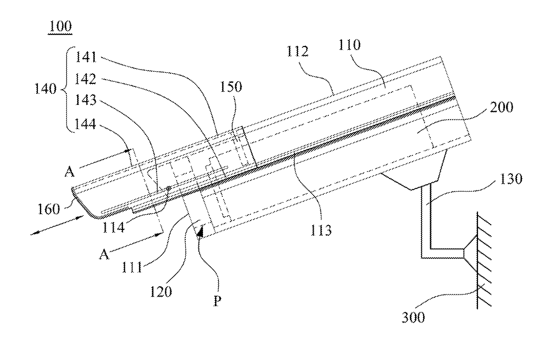
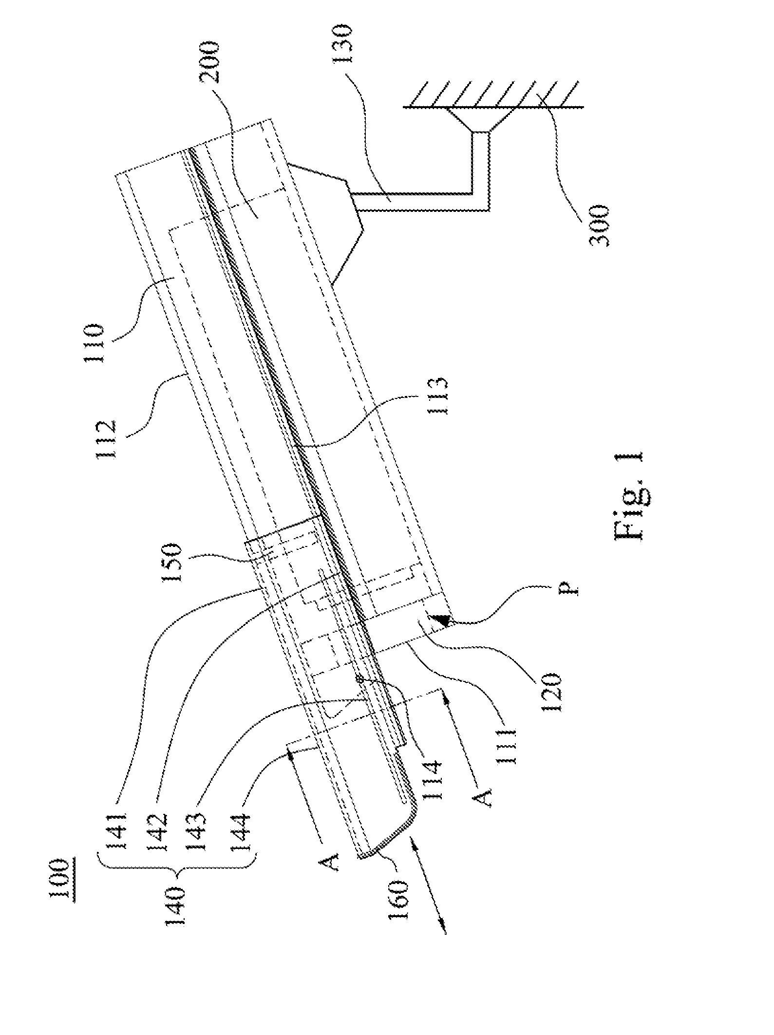
(1) In the embodiments of the present disclosure, a shield is slidably connected to the main housing and capable of sliding to extend outwards from the front face. That means the extension of the shield from the front face can be adjusted according to different outdoor conditions. Thus, the shield can effectively prevent any unwanted light from entering into the monitoring system and unwanted substances like rainwater and dust from sticking on the light transmission member and blocking the view of the scene the monitoring system is capturing.
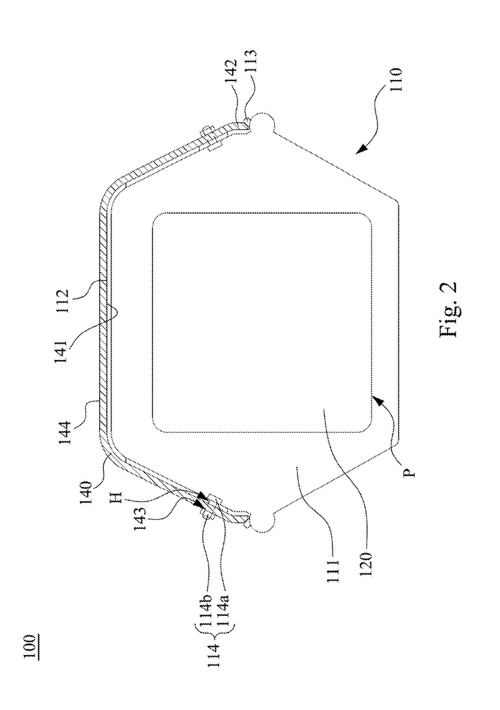
(2) In the embodiments of the present disclosure, a profile along the first surface of the main housing fits in shape with a profile along the second surface of the shield. Therefore, there is no seam between the main housing and the shield. When rainwater falls on the top of the main housing, it cannot flow through between the main housing and the shield. Thus, the rainwater falling on the top of the main housing cannot reach the front face of the main housing and block the view of the scene the monitoring system is capturing.
(3) Since the position of the shield relative to the main housing is fixed simply by a locking member locking the shield to the main housing, the operation is simple and easy especially in outdoor conditions.

Method used


Image

  • Housing assembly
  • Housing assembly
  • Housing assembly

Examples


Embodiment Construction

[0025]Drawings will be used below to disclose a plurality of embodiments of the present disclosure. For the sake of clear illustration, many practical details will be explained together in the description below. However, it is appreciated that the practical details should not be used to limit the claimed scope. In other words, in some embodiments of the present disclosure, the practical details are not essential. Moreover, for the sake of drawing simplification, some customary structures and elements in the drawings will be schematically shown in a simplified way. Wherever possible, the same reference numbers are used in the drawings and the description to refer to the same or like parts.

[0026]Unless otherwise defined, all terms (including technical and scientific terms) used herein have the same meaning as commonly understood by one of ordinary skill in the art to which this disclosure belongs. It will be further understood that terms, such as those defined in commonly used diction...


PUM


Abstract

A housing assembly for a monitoring system is provided. The housing assembly includes a main housing, a light transmission member, an adjustable arm and a shield. The main housing has a front face. The main housing has an opening located on the front face. The monitoring system is located in the main housing. The light transmission member is assembled with the opening, in which the monitoring system monitors via the light transmission member.The adjustable arm is connected to the main housing and a fixed object outside the main housing for adjusting an orientation of the main housing relative to the fixed object. The shield is slidably connected to the main housing and capable of sliding to extend outwards from the front face.

Description

BACKGROUND[0001]1. Technical Field[0002]The present disclosure relates to a housing assembly. More particularly, the present disclosure relates to a housing assembly for a monitoring system.[0003]2. Description of Related Art[0004]In recent years, video surveillance has been widely used in various public facilities like roads, homes, shopping malls, factories and hospitals as an important mechanism for deterring crime and safety protection. Due to the wide range of application requirements of monitoring systems, a particular protective cover is usually designed for the corresponding monitoring system in order to prevent any unwanted light from getting into the photosensitive element of the monitoring system. This protective cover can also prevent unwanted substances like rainwater and dust from sticking on the light transmission member and blocking the view of the scene the monitoring system is capturing.[0005]At present, there are two modes of protective cover. One is directly form...

Claims


Application Information

Patent Timeline
IPC IPC(8): H04N5/225H04N7/18
CPCH04N7/183H04N5/2252H04N23/51
Inventor HUANG, YU-LIN
Owner HUANG YU LIN
Learn More