Spatial light modulator including nano-antenna electrode and display apparatus including the spatial light modulator

a technology nano-antenna electrode, which is applied in the field of spatial light modulator, can solve problems such as difficulty in reducing the size of pixels

Active Publication Date: 2015-11-19
SAMSUNG ELECTRONICS CO LTD
View PDF8 Cites 27 Cited by
  • Summary
  • Abstract
  • Description
  • Claims
  • Application Information

AI Technical Summary

Benefits of technology

The invention relates to an improved design for a pixel electrode used in electronic devices such as displays or sensors. This new design includes a nanostructure that acts like an antenna to improve performance. The size of this nanostructure (measured by its width and length) should be small enough to match with the natural frequency at which it can vibrate without causing any interference. By incorporating these improvements into their device designs, researchers hope to create more efficient and effective electronics.

Problems solved by technology

The technical problem addressed in this patent text is the difficulty in reducing the size of pixels in a liquid crystal spatial light modulator to prevent interference of electric fields between adjacent pixels. This is because the liquid crystal cell requires a thickness of several micrometers in order to obtain a sufficient optical path to change the phase of light.

Method used


Image

  • Spatial light modulator including nano-antenna electrode and display apparatus including the spatial light modulator
  • Spatial light modulator including nano-antenna electrode and display apparatus including the spatial light modulator
  • Spatial light modulator including nano-antenna electrode and display apparatus including the spatial light modulator

Examples


Embodiment Construction

[0046]Hereinafter, a spatial light modulator including a nano-antenna electrode and a display apparatus including the spatial light modulator, according to one or more exemplary embodiments are described with reference to the accompanying drawings. In the drawings, unless otherwise suggested like reference numerals refer to like elements and a size of each element may be exaggerated for clarity. In this regard, the present embodiments may have different forms and should not be construed as being limited to the descriptions set forth herein. Also, when a layer is disposed “above” or “on” another layer, the layer may be directly on the other layer or one or more intervening layers may be present.

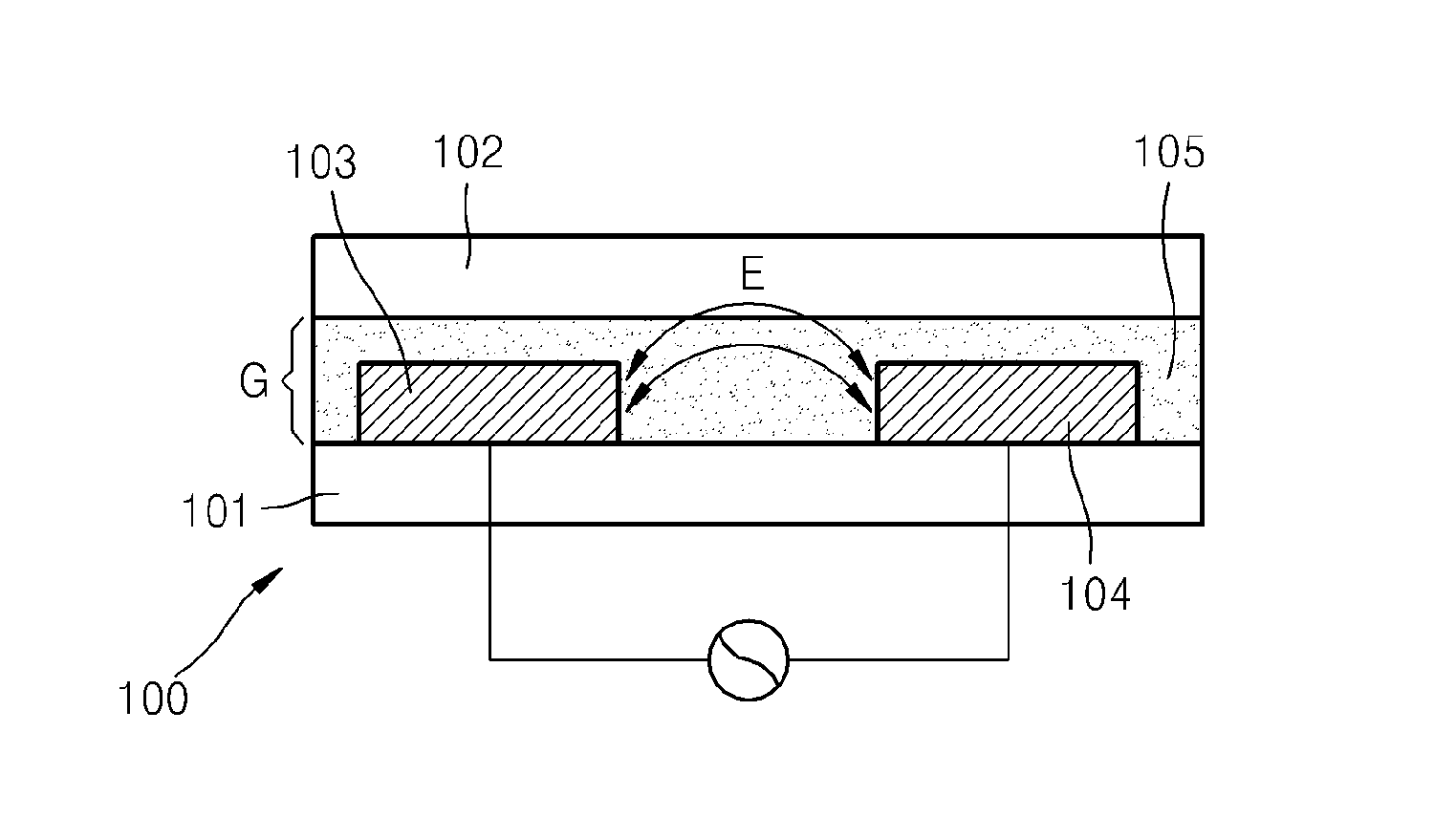
[0047]FIG. 1 is a cross-sectional diagram illustrating a spatial light modulator 100 according to an exemplary embodiment. In particular, FIG. 1 illustrates a part of one cell of the spatial light modulator 100. Referring to FIG. 1, the spatial light modulator 100 includes a first transparent ...


PUM


Abstract

A spatial light modulator including an electrode having a nano-antenna structure, and a display apparatus including the spatial light modulator are provided. The spatial light modulator includes a refractive index changing layer, and a pixel electrode and a common electrode which are configured to apply an electric field to the refractive index changing layer, and at least one of the pixel electrode and the common electrode include a nano-antenna pattern structure configured to resonate light.

Description


Claims


Application Information

Patent Timeline
Owner SAMSUNG ELECTRONICS CO LTD
Why Eureka
Try Eureka